A worked example — the ACI SP-273 hammerhead bent cap, rerun under ACI 318-25
ACI SP-273 Example 1 designs a single-column hammerhead bent cap with a simple strut-and-tie model under ACI 318-08 Appendix A. Here is the same cap and the same truss in AStrutTie, checked under ACI 318-25 — every number can be compared with a source you can open yourself, and the places where the newer code changes the answer are listed at the end.
Problem data (geometry, bearings, factored loads, materials) and the Model 1 truss are from ACI SP-273, Example 1: Bridge Pier – Hammerhead Bent Cap (R. G. Tuchscherer, M. D. Brown, O. Bayrak; American Concrete Institute, 2010), pp. 1–16. Figures and text are not reproduced; the model and every check below were run in AStrutTie under ACI 318-25.
Given
- f′c = 5,000 psi (34.5 MPa) · fy = 60,000 psi (414 MPa) · φ = 0.75
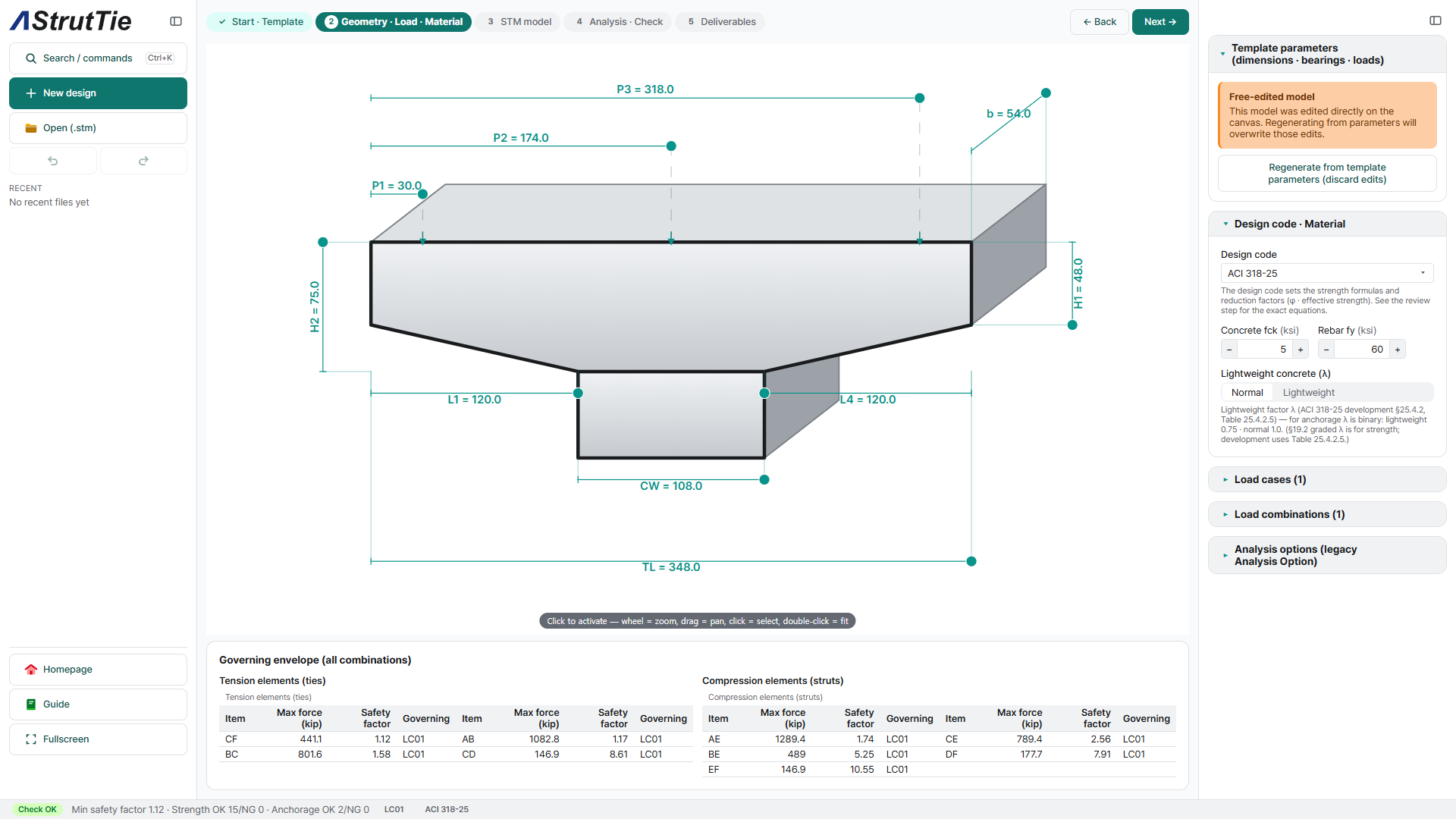
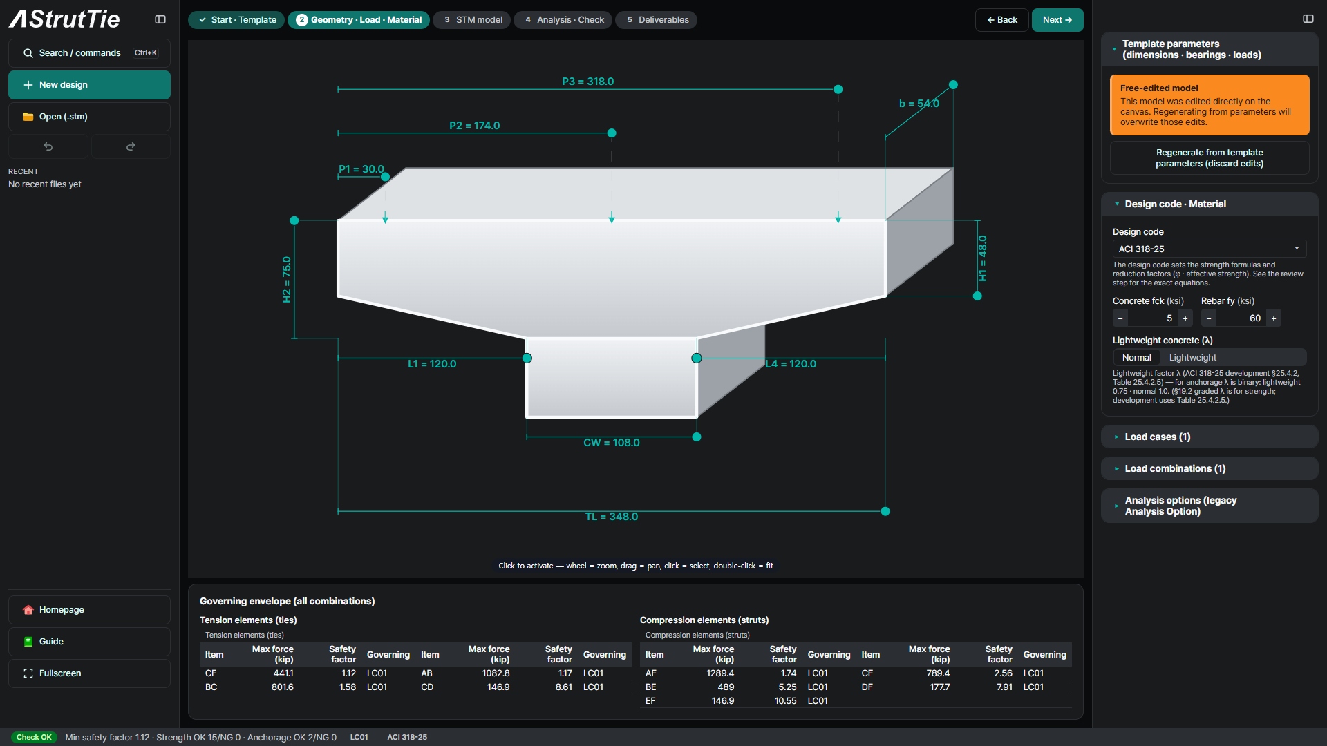
- Cap 29′-0″ long × 4′-6″ wide; 4′-0″ deep at the tips, 6′-3″ at the column; column 9′-0″ wide
- Bearings 30 × 36 in at 30, 174 and 318 in from the left tip
- Factored loads 700 · 400 · 100 kip — live load on one side only (the unbalanced case)
The problem
A single-column hammerhead cap carries three girder reactions out to the column. With 700 kip on the left and 100 kip on the right, both cantilevers are deep D-regions and an unbalanced moment goes into the column. Geometry and bearings are typed onto the drawing in kip and inch, as in the source.
Build the model — the SP-273 Model 1 truss
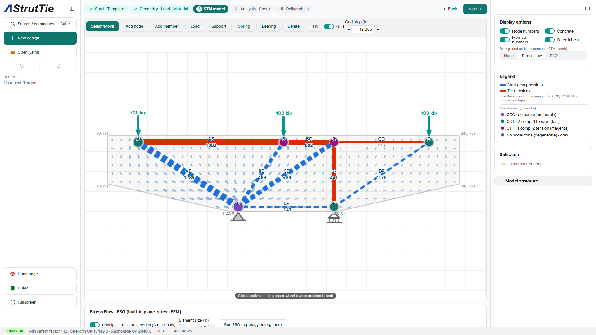
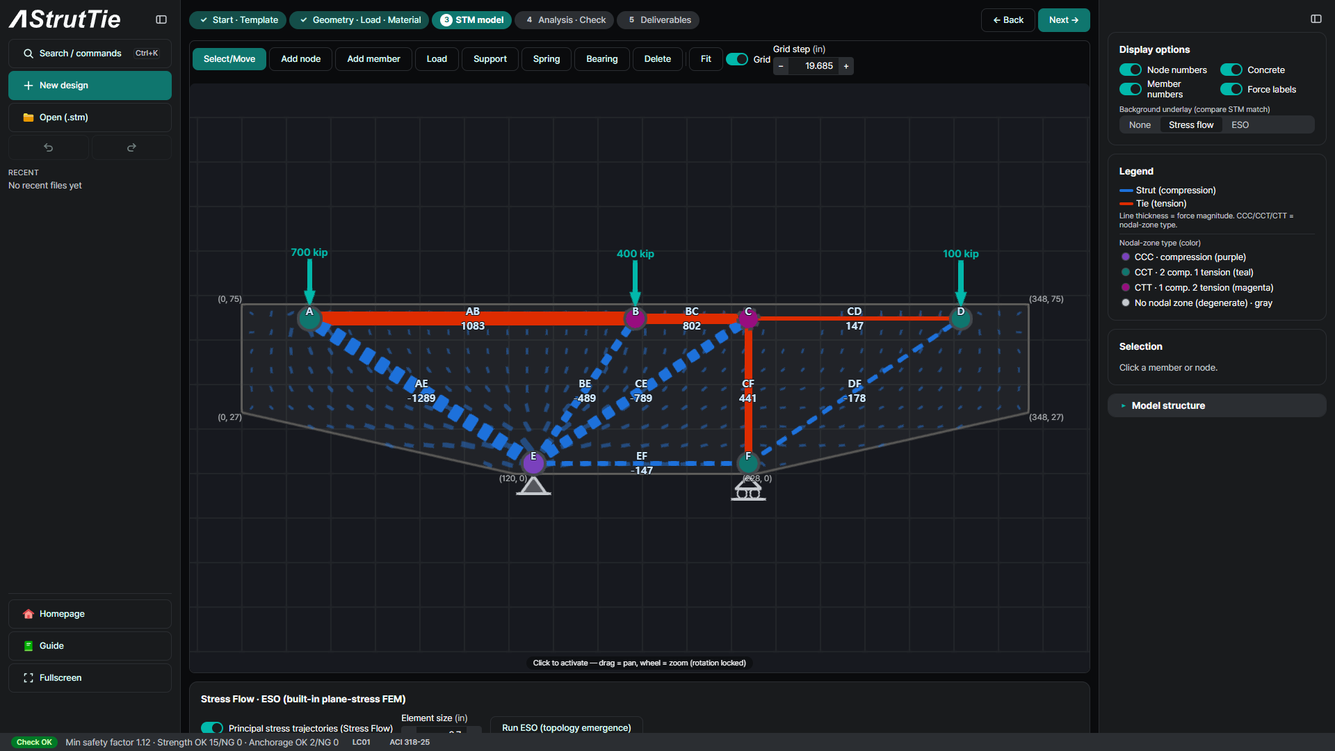
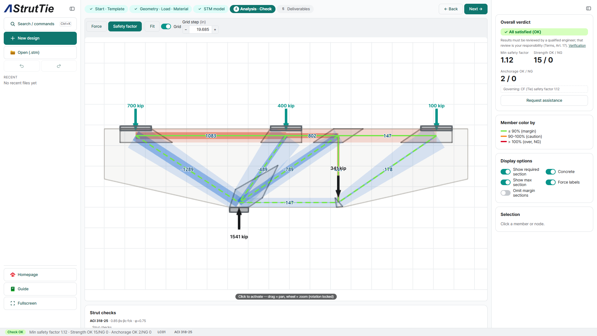
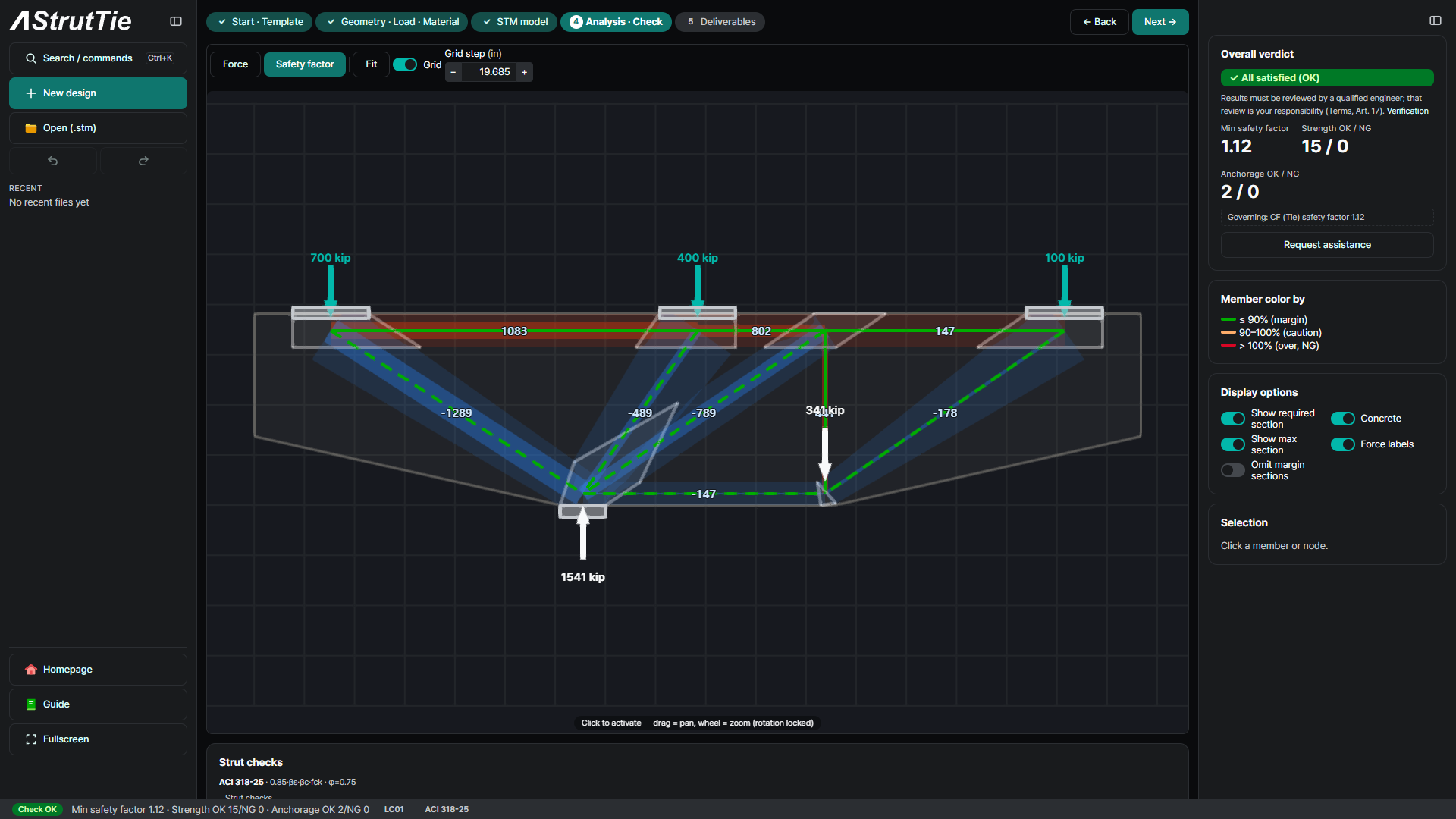
The pier-coping template gives a starting model, which was then edited node by node to the source's Model 1: tie ABCD 6.5 in below the top, struts from each bearing straight down to the column, and support nodes E and F set 9 in and 4 in inside the column faces. The analysis reproduces every member force in the source to the kip — AB 1,083 · BC 802 · CD 147 · AE −1,289 · BE −489 · CE −789 · DF −178 · CF 441 · EF −147. The underlay is the plane-stress flow of the same cap, for comparison.
Analyze & check — every member, every node
15 of 15 strength checks pass, minimum safety factor 1.12 (governing: vertical tie CF), and both hooked anchorages pass. The column reactions match the source as well: 1,541 kip compression at E and 341 kip tension at F.
Tie check — required reinforcement
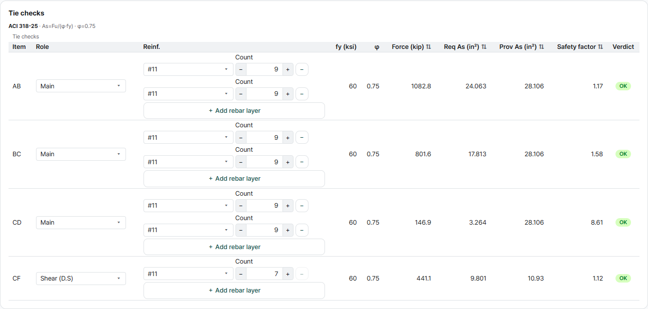
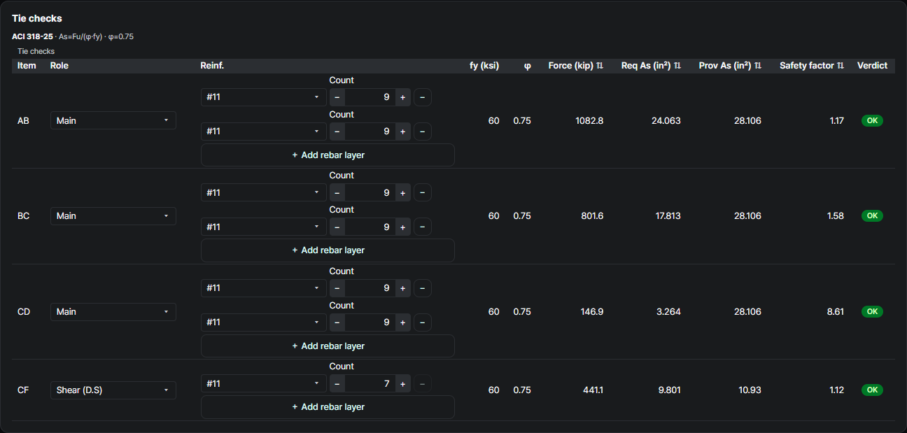
ACI 318-25Tie ABCD carries 1,082.8 kip and needs 24.06 in²; 18-#11 in two layers give 28.11 in² (safety factor 1.17) — the same bars and the same 24.1 in² as the source, because φ = 0.75 and the tie equation are unchanged. CF (441 kip) is the column's longitudinal steel running up into the cap. The source leaves it to the column design; here 7-#11 (10.93 in², safety factor 1.12) are assumed so the truss is complete.
Strut check — effective strength & width
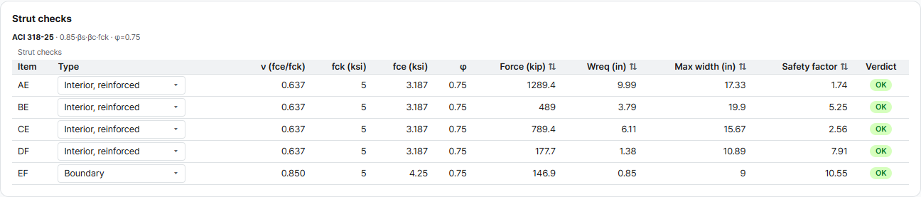
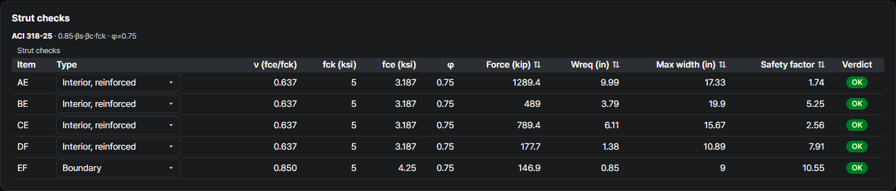
ACI 318-25Strut AE governs: 1,289 kip needs 9.99 in of width at fce = 3.19 ksi (interior strut, βs = 0.75), and 17.33 in is available at node E (safety factor 1.74). EF is a boundary strut (βs = 1.0). An interior strut keeps βs = 0.75 only with the distributed reinforcement of §23.5 — see step ⑧.
Nodal-zone check — by node type
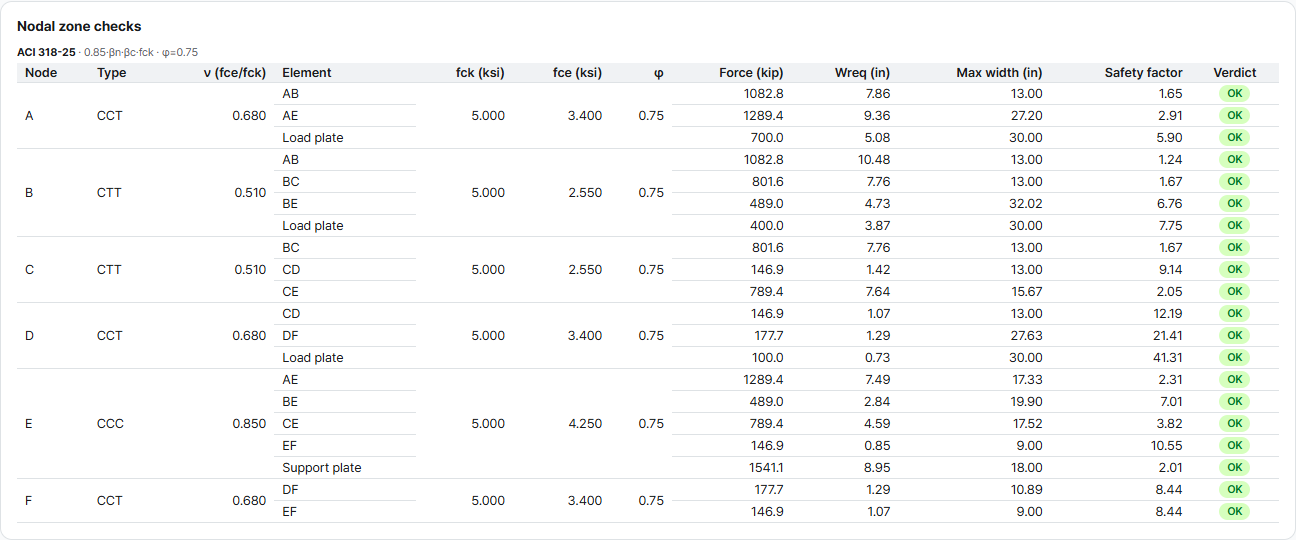
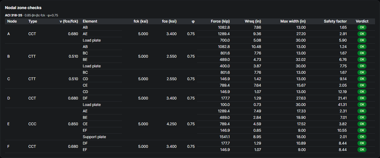
ACI 318-25A and D anchor one tie, B and C anchor two, E is all-compression. The lowest margin is the tie face at node B (safety factor 1.24); the 1,541 kip support face at E has 2.01.
| Node | βn | fce (ksi) |
|---|---|---|
| CCC (E) | 1.0 | 4.25 |
| CCT (A, D, F) | 0.8 | 3.40 |
| CTT (B, C) | 0.6 | 2.55 |
Anchorage check — hooked bars at the cap tips
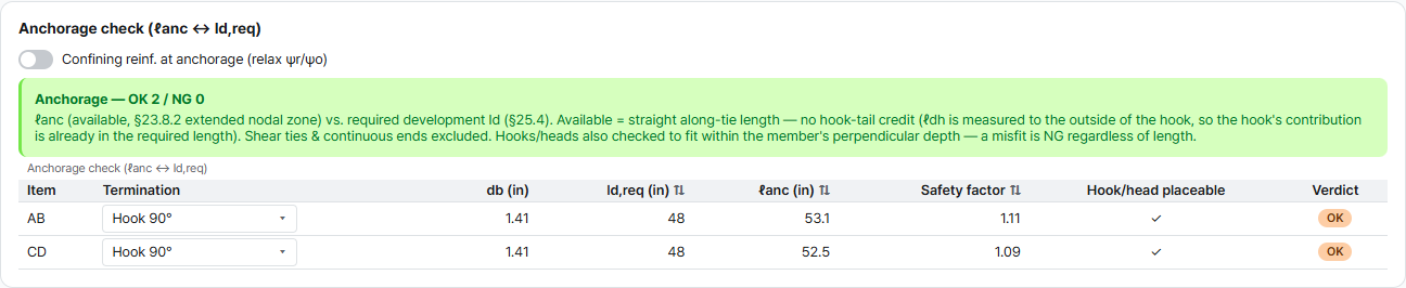
ACI 318-25 §23.8.2 · §25.4The 18-#11 end in standard 90° hooks. Under ACI 318-25 a #11 hook needs ℓdh = 48 in with no confining-reinforcement credit (ψr = 1.6, ψo = 1.25); the extended nodal zone gives ℓanc = 53.1 in at A (safety factor 1.11) and 52.5 in at D (1.09). The source, under ACI 318-08, needed only 23.9 in — the largest single change in this example.
What changes from the source
ACI 318-08 → ACI 318-25Same cap, same truss, same forces — the answer changes in three ways. Hooked anchorage roughly doubles. The source's crack-control grid (ratio 0.0021 each way) no longer meets §23.5, which asks for 0.0025 in each direction of an orthogonal grid: the cap is not laterally restrained, since 9 in of concrete beside a 36 in bearing is less than half the strut width. And two width assumptions differ — the source is the more conservative of the two in both.
| Check | SP-273 (ACI 318-08) | This example — ACI 318-25 | Why |
|---|---|---|---|
| Member forces (9) | AB 1,083 · AE −1,289 kip … | Identical | Same truss |
| Tie ABCD, 18-#11 | 24.1 in² required | 24.06 in² required | Same φ and tie equation |
| Hooked anchorage, #11 | ℓdh 23.9 in of 48.5 in | ℓdh 48 in of 53.1 in | Hook development reworked in ACI 318-19 |
| Distributed reinforcement | #5 4-leg @ 11 in + 7-#6 each face | #5 4-leg @ 9 in + #6 each face @ 6 in | §23.5: 0.0025 in each direction |
| Node A, tie face | 0.91 of capacity | 0.61 of capacity | Out-of-plane width: 36 in bearing (source) vs 54 in cap |
| Strut AE at node E | 0.83 of capacity | 0.58 of capacity | Face width: node E split, 12.1 in (source) vs full 18 in support, 17.3 in |
| Column bars CF | Left to the column design | 7-#11 assumed; anchorage in the cap left to the column / joint design | As in the source |
These are the checks AStrutTie runs on every model — here against a published example anyone can open, with the forces matching to the kip and every difference traced to a clause or an assumption. How we verify →
Try it on your own numbers
Open AStrutTie in your browser, sign in with your email and start from the same template. The Free plan needs no installation and no card.