A worked example — the ACI SP-208 dapped-end T-beam, rerun under ACI 318-25
ACI SP-208 Example 2 designs the dapped end of a precast T-beam that sits on an inverted T-beam ledge, with a nine-member strut-and-tie model under ACI 318-02 Appendix A. There is no template for a dapped end, so this one is drawn by hand in the app's free modeling: the outline, the nodes, the members, the supports and the loads. The member forces match the source, all 15 strength checks pass under ACI 318-25, and what the newer code changes is shown at the end.
Problem data (geometry, bearing plate, factored loads, materials) and the strut-and-tie model of the dapped end are from ACI SP-208, Example 2: Dapped-end T-beam supported by an inverted T-beam (D. H. Sanders; American Concrete Institute, 2002), pp. 91–103. Only the dapped end (the source's first model) is covered; the inverted T-beam ledge model is not, because the source gives its struts and plates different widths along the beam (7, 10 and 11.5 in), which a single-thickness 2D model cannot follow. Figures and text are not reproduced; the model and every check below were run in AStrutTie under ACI 318-25.
Given
- f′c = 5,500 psi (38 MPa) · fy = 60,000 psi (414 MPa) · φ = 0.75
- Web 10 in wide, 19 in deep; the dap leaves a 9 in deep nib, 7 in long
- Bearing plate 4 × 7 in under the nib, 3 in from its end
- Reaction 43.6 kip and a horizontal pull of 10 kip at the bearing · beam load 2.64 kip/ft (1.2D + 1.6L) split to the nodes as 1.5 · 2.2 · 2.9 kip
The problem
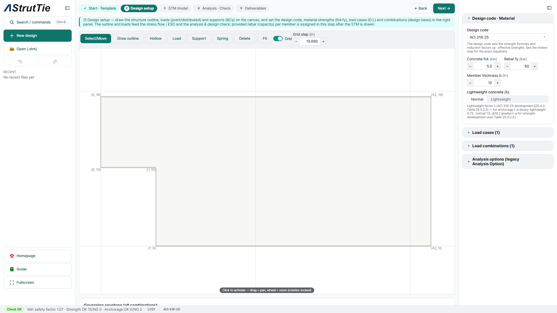
A dapped-end T-beam rests on the ledge of an inverted T-beam in a parking-structure frame. Within one depth of the dap the beam is a D-region; beyond it, ordinary beam design applies. With no template to start from, the outline is drawn directly in free modeling — a 7 in long, 9 in deep nib in front of the full 19 in section, which runs on to the right as the B-region.
Build the model — free modeling
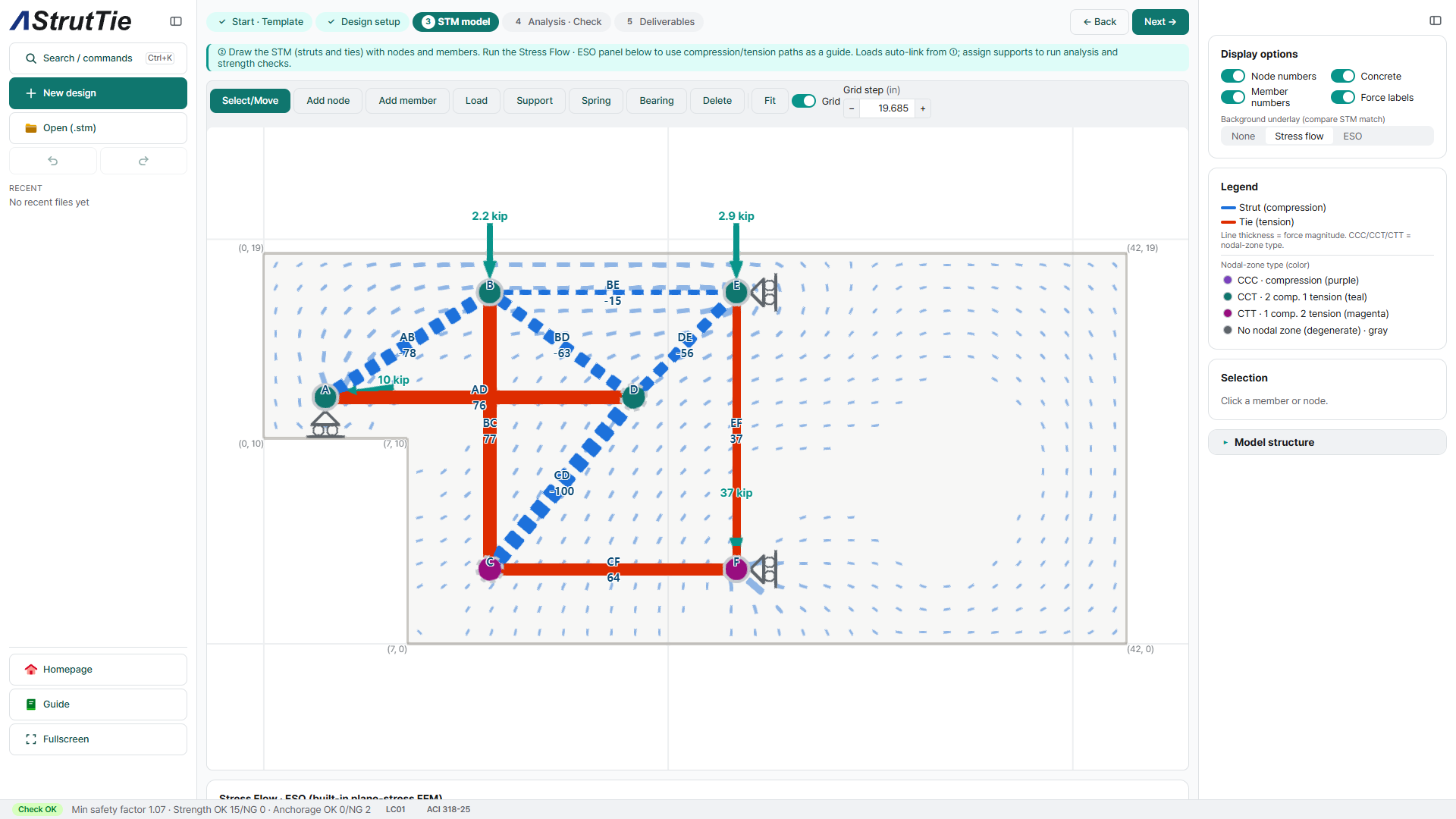
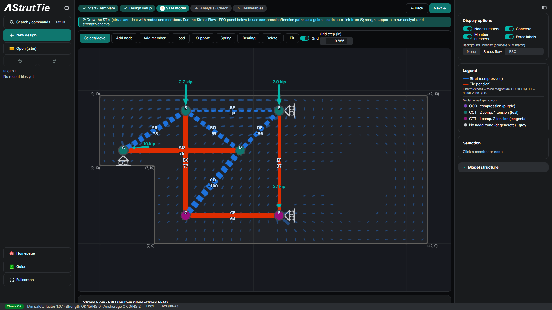
The nodes are placed at the source's coordinates: A at the bearing, 2 in above the nib soffit; B and E on the top strut, 1.9 in below the top; C and F on the bottom tie, 3.63 in above the bottom; D where tie AD meets the struts from B, C and E. A is the support. The section on the right is held horizontally at E and F, where the beam's compression and tension continue, and the 37.0 kip shear that the B-region carries is applied at F. The truss is statically determinate, and the forces are AB −78.3 · AD 76.0 · BD −62.9 · BE −15.2 · BC 76.9 · CD −100.3 · CF 64.3 · EF 37.0 · DE −55.9 kip, the source's to within its rounding.
Analyze & check — every member, every node
15 of 15 strength checks pass. The minimum safety factor is 1.07, in tie AD and in tie EF — the two ties the source also sized closest to their demand. Anchorage is reported separately from the strength verdict; the end plates the source uses on ties AD and CF are explained in step ⑦.
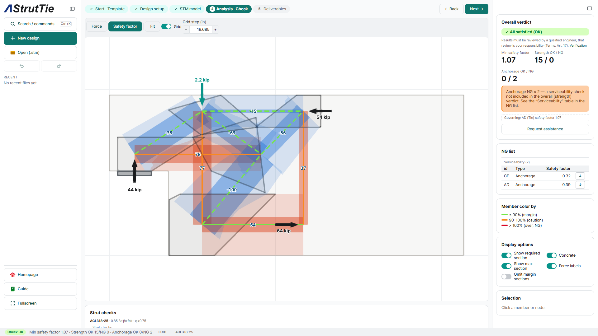
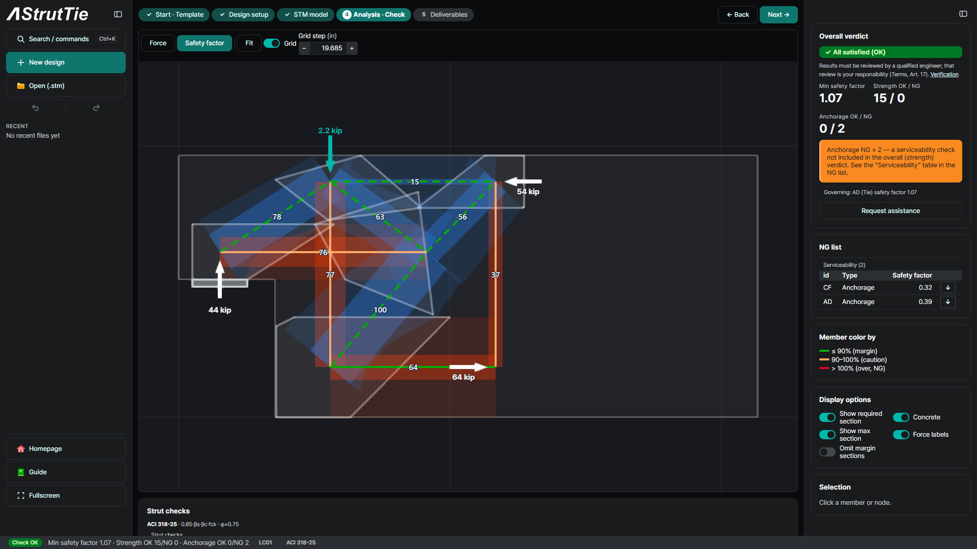
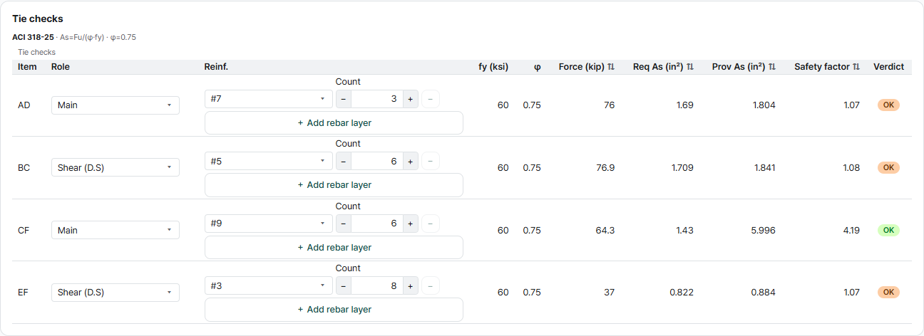
Tie check — required reinforcement
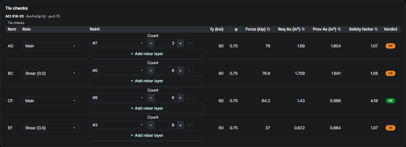
ACI 318-25Tie AD carries 76.0 kip and needs 1.69 in²; 3-#7 give 1.80 in² (safety factor 1.07), the source's bars. The hanger tie BC needs 1.71 in², as in the source, and its three #5 closed stirrups give 1.84 in² (1.08) — the app takes bar area from the nominal diameter, so the source's 1.86 in² reads 1% lower. The bottom tie CF needs 1.43 in² and has the full 6-#9 bottom steel, 6.00 in² (4.19). Tie EF needs 0.82 in² and is carried by four #3 stirrups at 4 in, 0.88 in² (1.07). BC and EF are stirrups, so they are checked for strength but not as anchored ties.
Strut check — effective strength & width
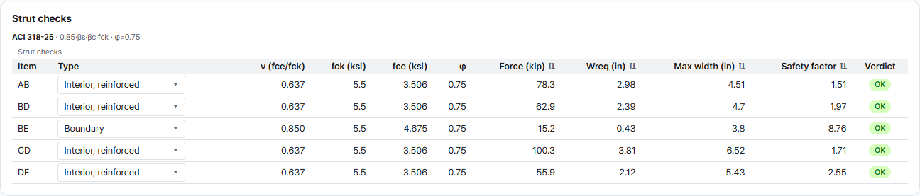
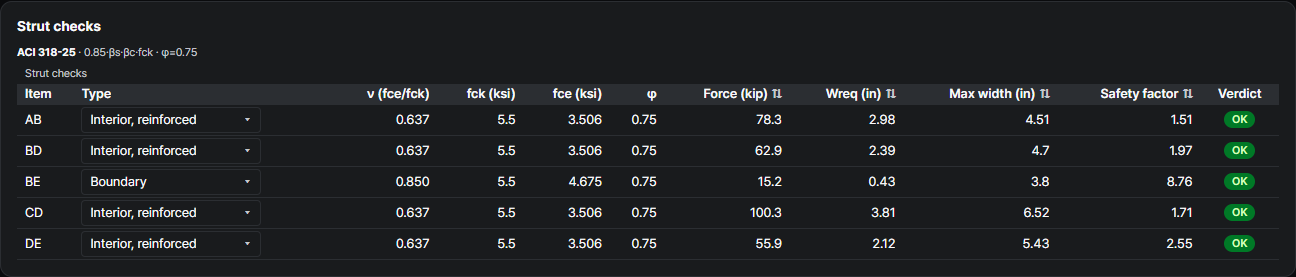
ACI 318-25 §23.4 · §23.5The interior struts AB, BD, CD and DE use βs = 0.75 (fce = 3.51 ksi) with the distributed reinforcement of §23.5 — step ⑧ shows the check. AB needs 2.98 in and has 4.51 in at node B (safety factor 1.51); at node A its width is 5.52 in, the same as the source's. BD needs 2.39 of 4.70 in (1.97), CD 3.81 of 6.52 in (1.71) and DE 2.12 of 5.43 in (2.55). The top strut BE is a boundary strut (βs = 1.0) and needs 0.43 of 3.80 in.
Nodal-zone check — by node type
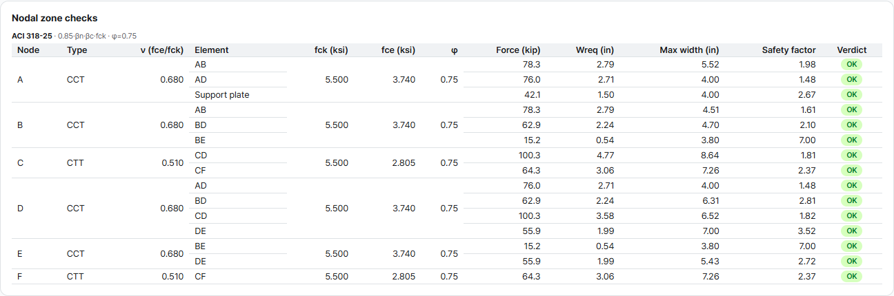
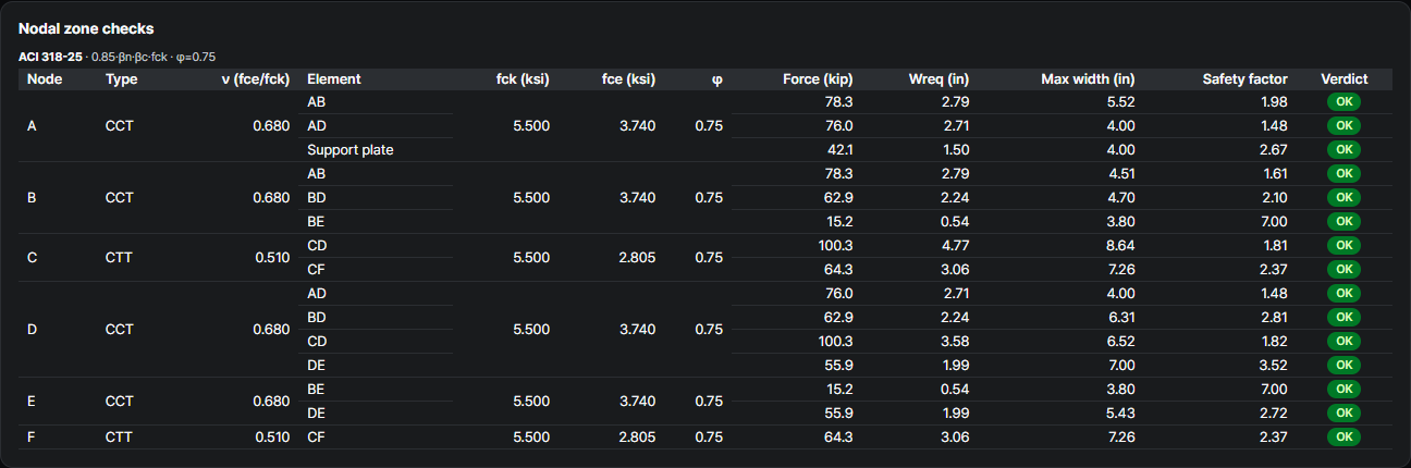
ACI 318-25The node types match the source: one tie anchored at A and B (βn = 0.8), two ties at C (0.6). At node A the bearing plate needs 1.50 of 4.00 in (2.67) and the face of tie AD 2.71 of 4.00 in (1.48); the app measures both through the 10 in web, where the source uses the 7 in width of the plate. Node B has 1.61, node C 1.81 at the face of strut CD. Nodes D, E and F are smeared in the source and not checked there; the app checks them, and all pass (1.48, 2.72, 2.37).
| Node | βn | fce (ksi) |
|---|---|---|
| CCT (A, B, D, E) | 0.8 | 3.74 |
| CTT (C, F) | 0.6 | 2.81 |
Anchorage check — where the app stops following the source
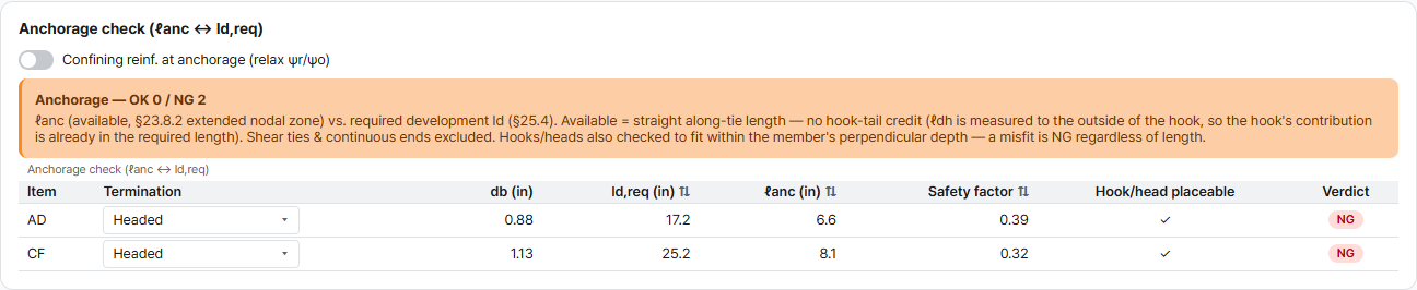
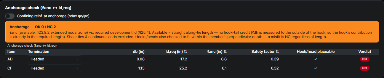
ACI 318-25 §23.8 · §25.4.4The nib is too short to develop ties AD and CF by bond, so the source welds 4 × 7 in and 5 × 7 in end plates to the bars and checks the bearing under each plate (79 and 73.6 kip). The app checks tie ends as straight, hooked or headed bars, so both ties were modeled as headed — the closest option. A #7 headed bar needs ℓdt = 17.2 in and the extended nodal zone at A leaves 6.6 in (safety factor 0.39); a #9 needs 25.2 in and node C leaves 8.1 in (0.32). An end plate is a mechanical anchorage, not a length check, so the NG is shown as the app reports it.
What changes from the source
ACI 318-02 → ACI 318-25Same dapped end, same truss, same forces. The main change is the interior strut factor. ACI 318-02 let the source use βs = 0.6 without distributed reinforcement; ACI 318-25 drops that value to 0.4, under which AB and CD would fail (1.24 and 1.10). To keep βs = 0.75, §23.5 must be met. In the nib, AB has no vertical bars, so the #3 ties at 2 in that the source called unnecessary are extended into the dap: ρ = 0.011 ≥ 0.0025 / sin² 57.5° = 0.0035. BD and DE are crossed by the #3 stirrups at 4 in: 0.0055 ≥ 0.0038 and 0.0051. CD meets the stirrups at 39.9°, just under the 40° of the one-direction rule, and is taken as satisfied by averaging the #5 stirrup at x = 13 in and the #3 at x = 17 in that cross it: ρ = 0.012 — a judgment call, stated here.
| Check | SP-208 (ACI 318-02) | This example — ACI 318-25 | Why |
|---|---|---|---|
| Member forces (9) | AB 78.2 · AD 76.0 · CD 100 kip … | AB 78.3 · AD 76.0 · CD 100.3 kip … | Same truss and statics |
| Tie AD, 3-#7 | 1.69 in² required, 1.80 provided | 1.69 in² required, 1.80 provided (1.07) | Same φ and tie equation |
| Tie BC, 3 #5 closed stirrups | 1.71 in² required, 1.86 provided | 1.71 in² required, 1.84 provided (1.08) | Bar area: nominal table (source) vs π·d²/4 (app) |
| Strut AB | βs = 0.6 · 5.52 in at A · 116 kip | βs = 0.75 · 5.52 in at A, 4.51 at B (1.51) | 0.6 is gone; 0.75 needs §23.5 — #3 ties at 2 in extended into the nib |
| Strut CD | βs = 0.6 · 7.2 in at C · 179 kip | βs = 0.75 · 6.52 in (1.71) | α₁ = 39.9°: §23.5 met by averaging the #5 and #3 that cross it (ρ 0.012) |
| Node A, bearing and tie face | 4 × 7 in plate: 79 kip for 43.6 and 75.9 kip | Plate 2.67 · tie face 1.48 | The app uses the 10 in web, the source the 7 in plate width |
| Node C (CTT) | βn = 0.6 · 5 × 7 in plate on tie CF, 73.6 kip | βn = 0.6 · CD face 1.81 · CF face 2.37 | Same node type |
| Anchorage of AD and CF | Welded end plates, plate bearing checked | Modeled as headed: AD 0.39 · CF 0.32 — NG | End plates are outside the app's termination model |
| Section on the right | Beam forces at the end of the D-region | E and F held horizontally · 37.0 kip shear at F | Equivalent statics: 54 kip compression at E, 64 kip tension at F |
These are the checks AStrutTie runs on every model — here on a dapped end drawn from scratch in free modeling, against a published example, with the forces matching the source and every difference traced to a clause, a convention or a judgment stated on the page. How we verify →
Try it on your own numbers
Open AStrutTie in your browser, sign in with your email and start from the same template. The Free plan needs no installation and no card.