A worked example — the ACI SP-208 corbel at a column, rerun under ACI 318-25
ACI SP-208 Example 3.1 designs a single corbel on a 14 in column with a six-member strut-and-tie model under ACI 318-02 Appendix A. The AStrutTie corbel template lands on the same truss, node for node. Here it is checked under ACI 318-25 — the forces match the source, the strength checks pass with the same governing node, and the one place the app cannot follow the source's detail is shown as it is.
Problem data (geometry, bearing plate, factored loads, materials) and the strut-and-tie model are from ACI SP-208, Example 3.1: Corbel at column (T. N. Tjhin, D. A. Kuchma; American Concrete Institute, 2002), pp. 105–115. Figures and text are not reproduced; the model and every check below were run in AStrutTie under ACI 318-25.
Given
- f′c = 5,000 psi (34.5 MPa) · fy = 60,000 psi (414 MPa) · φ = 0.75
- Column 14 × 14 in; corbel 14 in wide, projecting 9 in, 18 in deep at the column face and 9 in at the tip
- Bearing plate 12 × 6 in, 1 in from the column face
- Vu = 56.2 kip at 4 in from the face (moved to 5 in for erection tolerance) · Nuc = 11.2 kip outward at the top
The problem
A precast beam sits on a short corbel. The vertical reaction is 56.2 kip, and creep and shrinkage of the beam add an 11.2 kip horizontal pull at the bearing. With a shear span of 5 in over an effective depth of 16.4 in, the whole corbel is a D-region. The corbel template takes the column width, projection, the two depths and the load position directly — in kip and inch, as in the source.
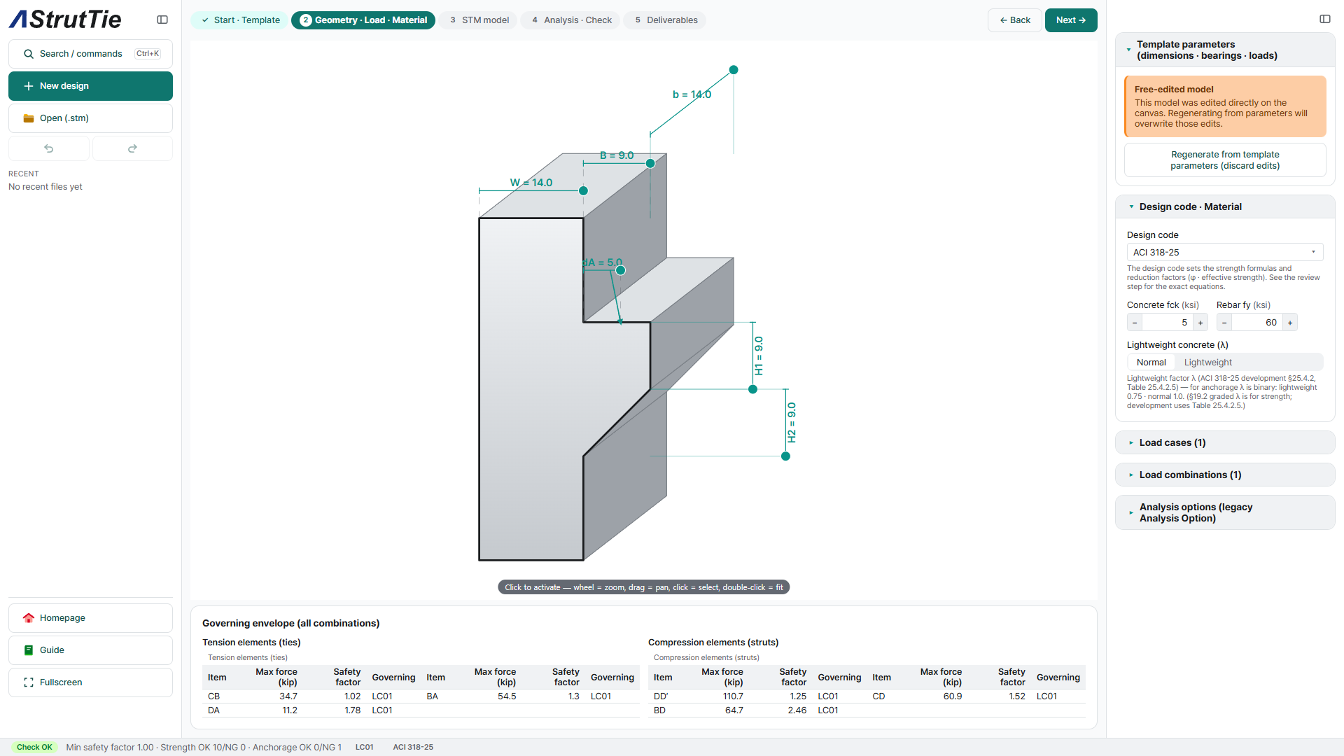
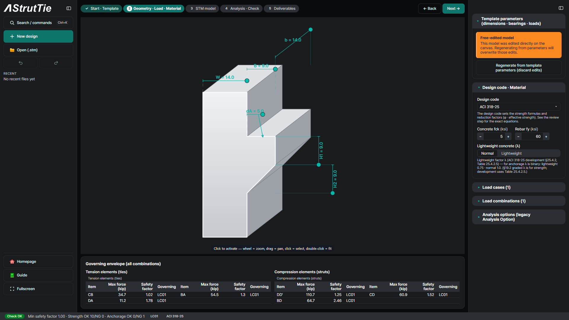
Build the model — the SP-208 truss
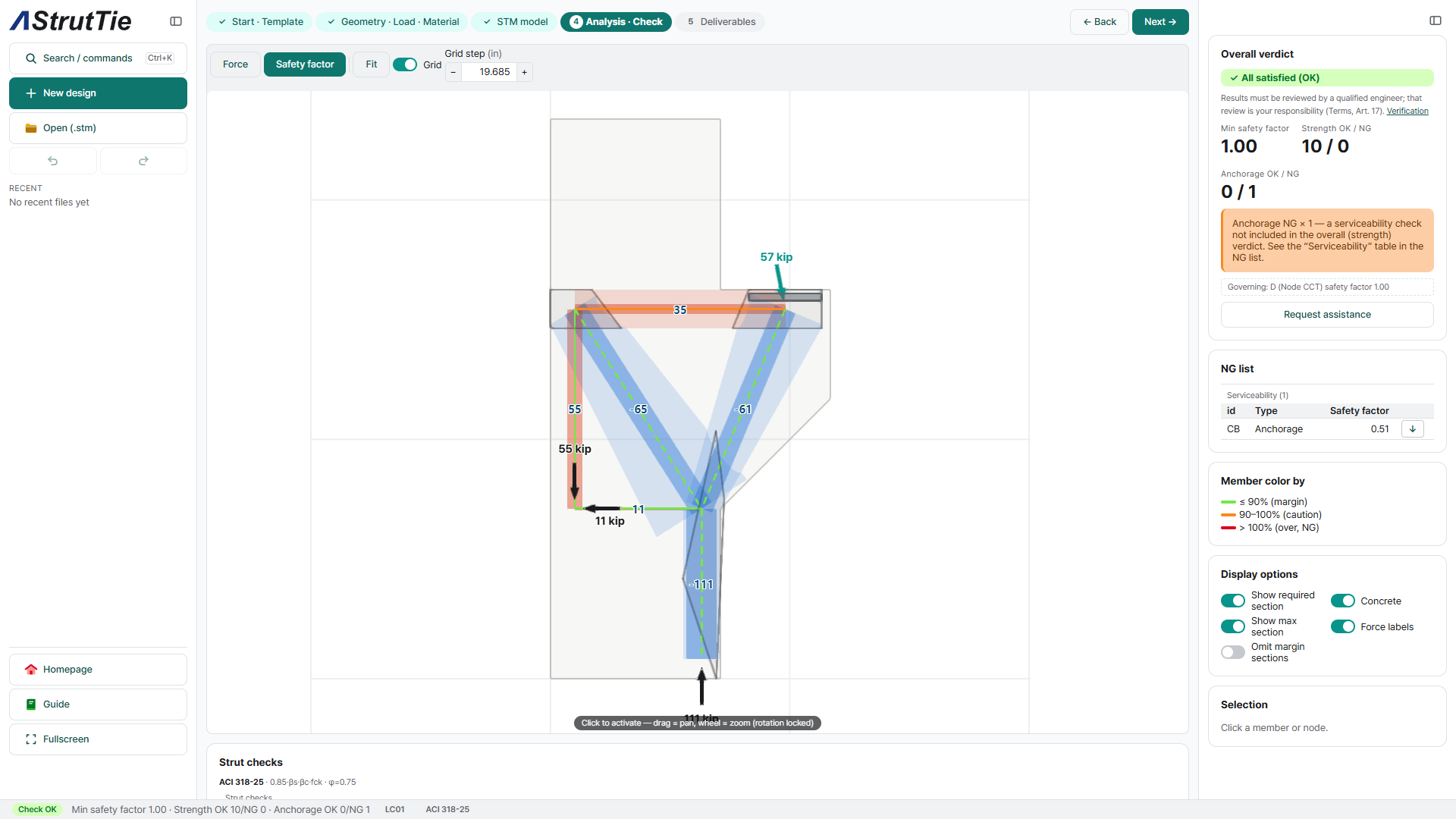
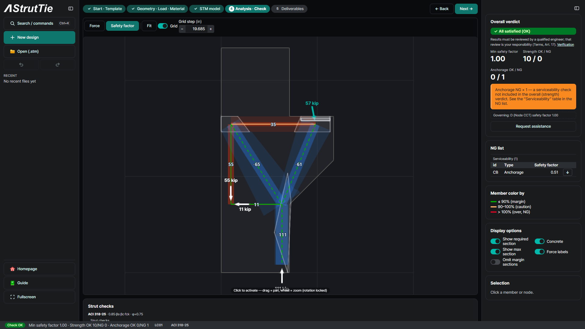
With the source's dimensions, the template puts every node where the source does: tie CB 1.6 in below the top, node C where the load resultant meets the tie (the 11.2 kip pull moves it 0.32 in further out, the same rule as the source), tie DA at the 18 in level, and strut DD′ running down the column 3.10 in wide. B and A sit 2 in inside the back face of the column. The template's three extra members inside the column were removed — the source leaves that region to the column design. The analysis gives CB 34.7 · CD −60.9 · BD −64.7 · BA 54.5 · DA 11.2 · DD′ −110.7 kip, the source's forces to within its rounding.
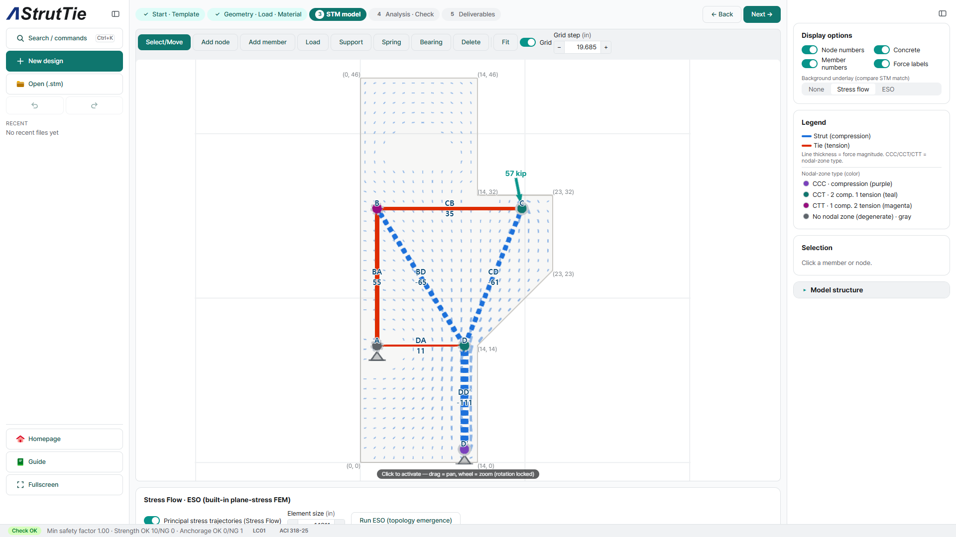
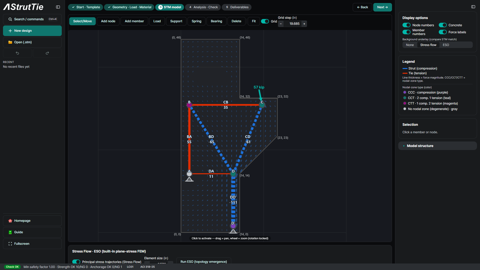
Analyze & check — every member, every node
10 of 10 strength checks pass. The minimum safety factor is 1.00, at the face of strut DD′ on node D — exactly where the source sized the strut width to the stress limit. Anchorage is reported separately from the strength verdict, and the tie CB anchorage does not pass as modeled; step ⑦ explains why.
Tie check — required reinforcement
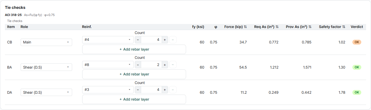
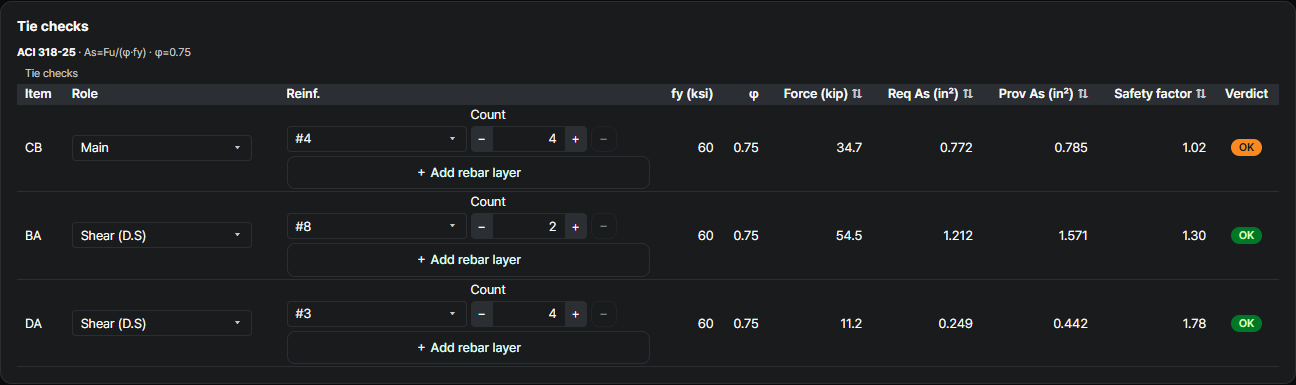
ACI 318-25Tie CB carries 34.7 kip and needs 0.772 in²; 4-#4 give 0.785 in² (safety factor 1.02) — the same bars and the same 0.77 in² as the source. BA is the column's longitudinal steel on the back face; the source leaves it to the column design, and 2-#8 (1.57 in², safety factor 1.30) are assumed here. DA is carried by two #3 column ties (four legs, 0.442 in², safety factor 1.78), as in the source.
Strut check — effective strength & width
ACI 318-25CD and BD are interior struts (βs = 0.75, fce = 3.19 ksi). CD needs 1.82 in and has 2.77 in at node D (safety factor 1.52); BD needs 1.93 in — the same as the source — and has 4.74 in (2.46). DD′ is a boundary strut (βs = 1.0): 2.48 in needed, 3.10 in available (1.25). Interior struts keep βs = 0.75 only with the distributed reinforcement of §23.5 — see step ⑧.


Nodal-zone check — by node type
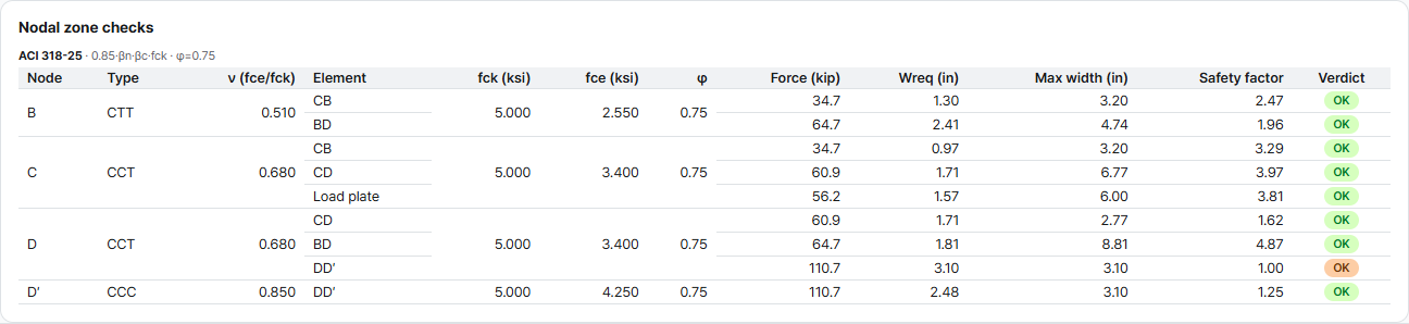
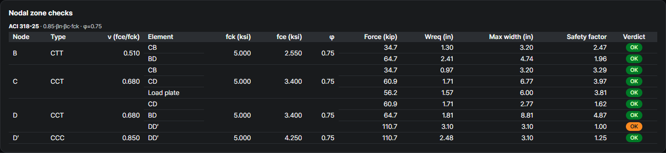
ACI 318-25Node D governs: strut DD′ needs 3.10 in and 3.10 in is there (safety factor 1.00), because the source chose that width to put the node exactly at its limit. At node C the tie needs 0.97 in of the 3.20 in available (3.29) and the bearing plate 1.57 in of 6 in (3.81). Node B, which the source does not check, has 1.96.
| Node | βn | fce (ksi) |
|---|---|---|
| CCC (D′) | 1.0 | 4.25 |
| CCT (C, D) | 0.8 | 3.40 |
| CTT (B) | 0.6 | 2.55 |
Anchorage check — where the app stops following the source
ACI 318-25 §23.8 · §25.4.4The source welds the four #4 bars to a 3½ × 3½ × ½ in steel angle at the front face, and bends them down into the column at the back. The app checks tie ends as straight, hooked or headed bars, so CB was modeled with headed ends — the closest option. A #4 headed bar needs ℓdt = 7.5 in; the extended nodal zone leaves 6.35 in at C (safety factor 0.84) and 3.8 in at B (0.51) inside a corbel that projects only 9 in. Neither of the source's details is a length check: the welded angle is a mechanical anchorage, and at B the bars continue down the column. The NG is shown as the app reports it.


What changes from the source
ACI 318-02 → ACI 318-25Same corbel, same truss, same forces. The tie and node limits have not changed, so the governing node lands at the same 1.00. What differs is how widths are measured — the app takes them from the nodal-zone geometry, where the source drew them by hand or picked the minimum — and the anchorage detail, which the app cannot represent. The distributed-reinforcement rule has a new form, and the source's three #3 hoops pass it as well.
| Check | SP-208 (ACI 318-02) | This example — ACI 318-25 | Why |
|---|---|---|---|
| Member forces (6) | CB 34.8 · CD −60.9 · DD′ −111 kip … | CB 34.7 · CD −60.9 · DD′ −110.7 kip … | Same truss; the source rounds the 0.32 in offset |
| Tie CB, 4-#4 | 0.77 in² required | 0.772 in² required (1.02) | Same φ and tie equation |
| Node D, face of DD′ | ws = 3.10 in sized to the limit | 3.10 of 3.10 in (1.00) | Same βn = 0.8 |
| Strut CD | Ac = 14 × 2.86 in, 0.63 of capacity | 2.77 in at node D, 0.66 of capacity | Width drawn by hand (source) vs the app's nodal zone |
| Strut BD | 1.93 in required, 2 in chosen | 1.93 in required, 4.74 in available | The source picks the minimum width |
| Bearing, 12 × 6 in plate | 781 of 2,550 psi | Safety factor 3.81 | Out-of-plane width: plate 12 in (source) vs corbel 14 in |
| Distributed reinforcement | Σ ρ sin γ = 0.0038 ≥ 0.003 | ρ = 0.0045 ≥ 0.0025 / sin² 57.5° = 0.0035 | §23.5 one-direction rule; the same 3 #3 hoops @ 3.5 in pass |
| Anchorage of tie CB | Welded steel angle (front), bent down the column (back) | Modeled as headed: 0.84 at C, 0.51 at B — NG | Welded angles and bars bent through the node are outside the app's termination model |
These are the checks AStrutTie runs on every model — here against a published example anyone can open, with the forces matching the source and the one detail the app cannot follow shown as it is. How we verify →
Try it on your own numbers
Open AStrutTie in your browser, sign in with your email and start from the same template. The Free plan needs no installation and no card.