A worked example — the PCA square spread footing, rerun under AASHTO LRFD 2024
PCA EB231 Example 2 designs a 9 × 9 ft spread footing, 3 ft thick, under a 30 in square column, with a strut-and-tie model under AASHTO LRFD. AStrutTie has no template for that truss, so it was drawn node for node as a free model, with two zero-force members added to close it. Checked under AASHTO LRFD 2024, the forces match the source, every strength check passes with the bottom tie governing, and the hooked-bar anchorage is the one check whose verdict changes.
Problem data (geometry, materials, factored load) and the strut-and-tie model are from PCA EB231, AASHTO LRFD Strut-and-Tie Model Design Examples, Example 2: Design of Footing (Mitchell, Collins, Bhide, Rabbat; Portland Cement Association, 2004), pp. 2-1–2-7. Figures and text are not reproduced; the model and every check below were run in AStrutTie under AASHTO LRFD 2024.
Given
- f′c = 4,000 psi (27.6 MPa) · fy = 60,000 psi (414 MPa) · φ = 0.70 for compression, 0.90 for tension
- Footing 9 × 9 ft, 3 ft thick · column 2 ft 6 in square at the center
- Factored column load 714 kip, including the column's own weight · column moment neglected, as in the source
- Uniform soil pressure: nine reactions of 79.3 kip at 1 ft spacing · bottom bars 8-#8 each way, 3 in cover, 180° hooks
The problem
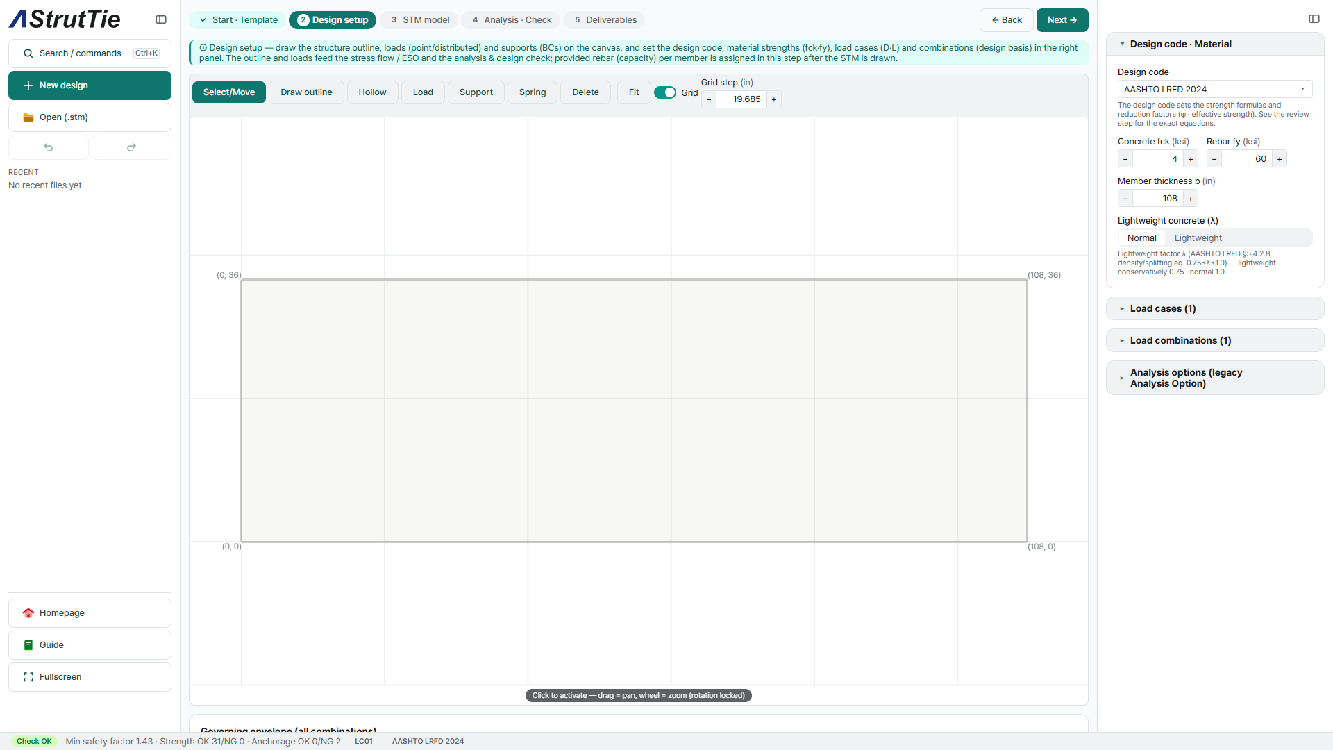
A square spread footing carries a column load into the ground. Footings are usually designed for flexure and shear at critical sections; the source uses a strut-and-tie model to follow the flow of forces instead. No AStrutTie template builds this truss, so the outline — 108 × 36 in — was drawn as a free model, in kip and inch as in the source, with the full 108 in width of the footing as the member thickness.
Build the model — the PCA truss
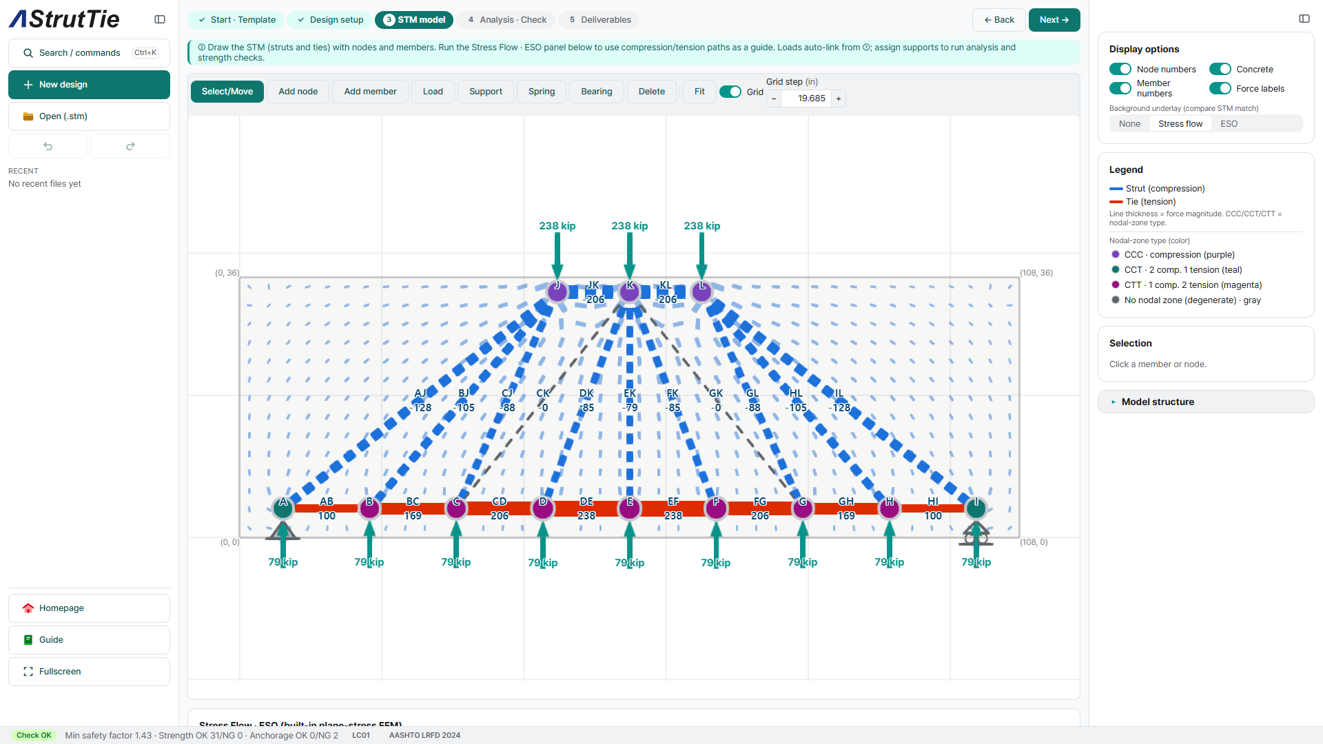
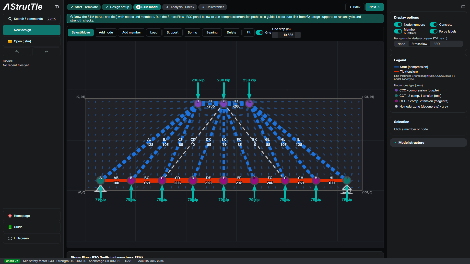
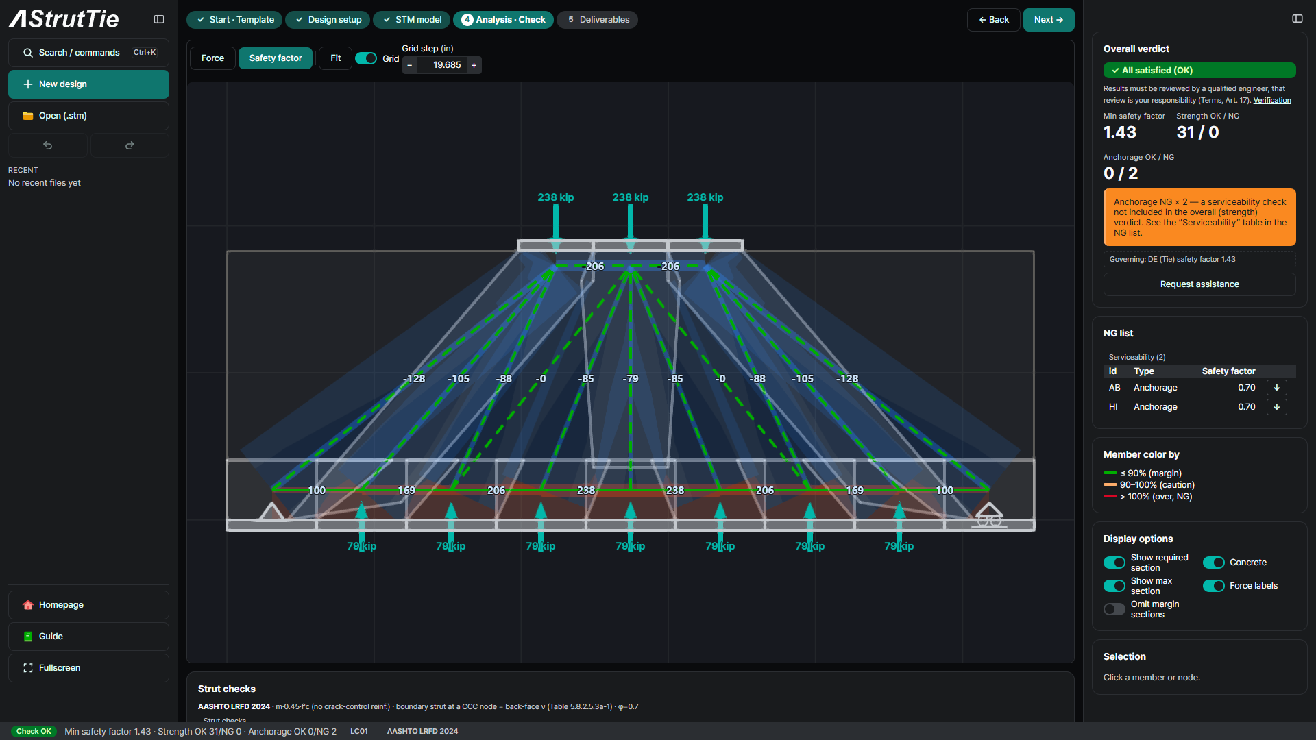
The source puts the tie 4 in above the bottom and the top strut 2 in below the top, a lever arm of 30 in. The soil pressure is uniform, so it enters as nine reactions of 79.3 kip at nodes A–I, 1 ft apart. The column load is split into three forces of 238 kip at J, K and L, each the resultant of a 10 in third of the column, and each top node fans out to three bottom nodes. That truss is a mechanism — the panels J–C–D–K and K–F–G–L have no diagonal — and it stands only because every top node carries exactly three reactions. The app would solve it as a lower-bound equilibrium and flag it, so two members, CK and GK, were added to close it; under this load they carry nothing. The supports at A and I only hold the model in place: with the loads in equilibrium they take no reaction. The analysis gives AJ −128.0 · BJ −105.0 · CJ −87.5 · DK −85.4 · EK −79.3 kip in the struts and 100.5 · 169.2 · 206.3 · 238.0 kip along the tie, the source's forces to within its rounding.
Analyze & check — every member, every node
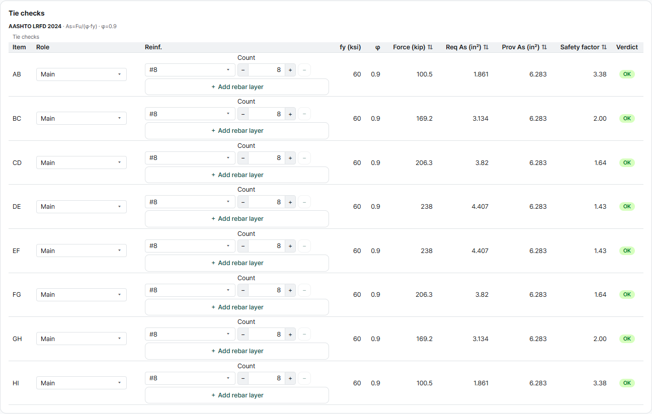
31 of 31 strength checks pass. The minimum safety factor is 1.43, on the bottom tie DE–EF under the column. Every strut and node keeps a wide margin; the tightest is the top strut JK at 2.64. Anchorage is reported separately from the strength verdict, and both hooked ends of the tie fail it; step ⑦ explains why.
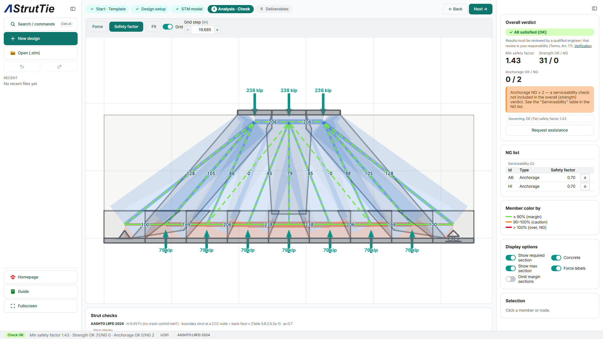
Tie check — required reinforcement
AASHTO LRFD 2024Ties DE and EF carry 238 kip and need 4.41 in², the source's value. The source then raises the steel to 1.33 times that, 5.87 in², because the minimum flexural reinforcement for 1.2 Mcr (8.30 in²) would otherwise govern, and chooses 8-#8 each way. The app takes a bar's area as π·d²/4 = 0.785 in², so the eight bars give 6.28 in² rather than the source's 6.32 in²: a safety factor of 1.43. The flexural minimum is a separate check from the strut-and-tie checks, and the app does not run it.
Strut check — effective strength & width
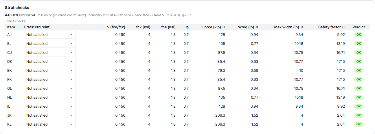
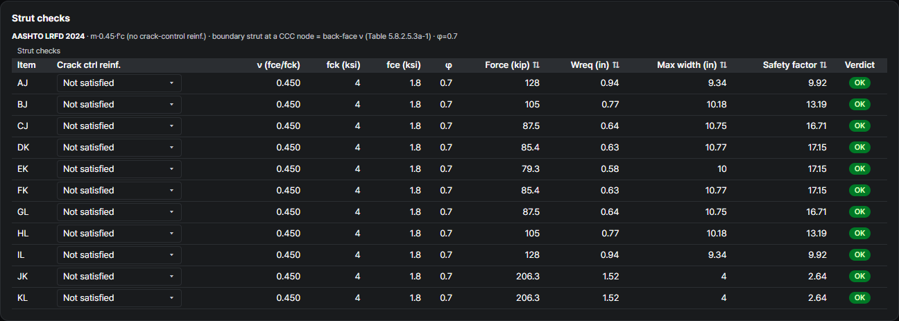
AASHTO LRFD 2024 Table 5.8.2.5.3a-1A footing needs no crack control reinforcement, and this one has none, so every strut-to-node interface takes ν = 0.45: fce = 1.80 ksi with φ = 0.70. The source used the strain-based strut limit of its edition: for strut AJ, with the tie strain at node A, fcu = 2.73 ksi on a width of 12 in · sin 38.3° = 7.4 in, so φPn = 1,527 kip against 128 kip. The 2024 edition drops that limit and checks a strut where it meets a node. AJ needs 0.94 in; the app finds 13.71 in at node A, where the tie's 8 in height adds to the bearing length the source used, and 9.34 in at node J, which governs: a safety factor of 9.92. The top struts JK and KL, 4 in deep, carry 206.3 kip and are the tightest at 2.64.
Nodal-zone check — by face and node type
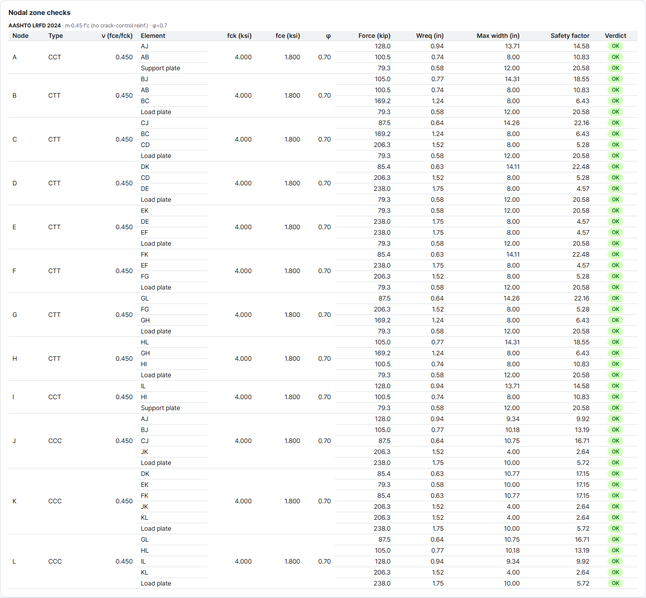
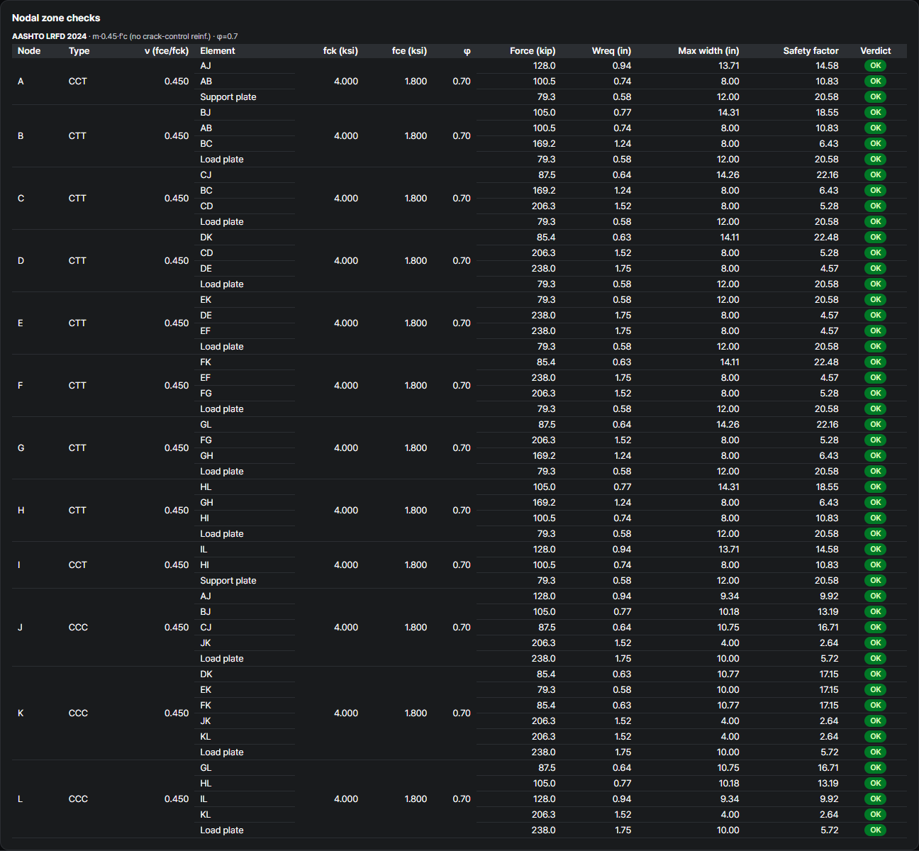
AASHTO LRFD 2024 Table 5.8.2.5.3a-1ν by face, for f′c = 4 ksi. Without crack control reinforcement every face takes 0.45. Nodes J, K and L, where the column frames in, are CCC; the source calls them not critical and does not check them. The app checks them: the 4 in face of the top strut needs 1.52 in (2.64) and the column bearing 1.75 of 10 in (5.72). At node A, a CCT node, the source checks the tie's anchorage face, 0.12 ksi against 2.1 ksi. The app has the same face at 0.74 of 8 in (10.83) — a smaller margin, because ν drops from 0.75 to 0.45. Along the tie, nodes B–H are CTT; the most loaded, D–F, have 4.57.
| Face | With crack control reinforcement | Without |
|---|---|---|
| CCC — bearing · back face | 0.85 | 0.45 |
| CCT — bearing · back face | 0.70 | 0.45 |
| CTT — bearing · back face | 0.65 | 0.45 |
| Strut-to-node interface | 0.65 | 0.45 |
Anchorage check — the 2024 development equation
AASHTO LRFD 2024 §5.8.2.4.2 · §5.10.8.2.4aThe tie ends in 180° hooks, #8 with 3 in cover. The source looks at the critical section 12 in from the edge, finds only 15.9 ksi in the bars there (100.5 kip on 8 × 0.79 in²), and judges the 9 in left to the end of the hook enough to develop it. The app measures the available length along the tie from the extended nodal zone, 14.1 in, and asks for the 2024 development length of a #8 hook, 20.0 in, without the excess-reinforcement reduction: a safety factor of 0.70 at A and at I. The NG is shown as the app reports it.


What changes from the source
PCA EB231 (2004) → AASHTO LRFD 2024Same footing, same truss, same forces — with two zero-force members added so the model is stable. Every strength check passes under the 2024 edition, as it did in the source. The numbers move for known reasons: the strain-based strut limit is gone, a footing without crack control reinforcement takes ν = 0.45, the app checks the CCC nodes the source leaves out, the bar-area convention, and the development equation, which turns the hooked anchorage into the one NG.
| Check | PCA EB231 (2004) | This example — AASHTO LRFD 2024 | Why |
|---|---|---|---|
| Member forces | AJ −128 · BJ −105 · CJ −88 · DK −85 · EK −79.3 · DE 238 kip … | AJ −128.0 · BJ −105.0 · CJ −87.5 · DK −85.4 · EK −79.3 · DE 238.0 kip … | Same truss and statics |
| Model | 19 members, a mechanism that stands under this load | + CK · GK at 0 kip — statically determinate | The app flags a mechanism and solves it only as a lower bound |
| Tie DE, 8-#8 | 4.41 in² required · 6.32 in² provided | 4.407 in² required · 6.283 provided (1.43) | Same φ = 0.90 · bar area π·d²/4 in the app |
| Minimum flexural reinforcement | 1.33 × 4.41 = 5.87 in² ≤ 6.32 in² | Not part of the STM checks | A hand check outside the app |
| Strut AJ | fcu 2.73 ksi · w 7.4 in · φPn 1,527 ≥ 128 kip | fce 1.80 ksi · 9.34 in at J (9.92) | No strain-based strut limit in 2024 · ν 0.45 · width from the nodal zone |
| Nodes J · K · L (CCC) | Not critical — not checked | Top-strut face 2.64 · column bearing 5.72 | The app checks every node |
| Node A (CCT), tie face | 0.12 ≤ 2.1 ksi | 0.74 of 8 in (10.83) | ν 0.75 → 0.45 without crack control reinforcement |
| Crack control reinforcement | Footings exempt | Taken as not provided — ν = 0.45 on every face | Table 5.8.2.5.3a-1 |
| Hooked #8 anchorage at A | 15.9 ksi in the bars · 9 in to the hook end enough | 20.0 in required > 14.1 in (0.70) — NG | 2024 development equation; no excess-reinforcement reduction in the app |
These are the checks AStrutTie runs on every model — here against a published example anyone can open, with the forces matching the source and every difference traced to a clause, a convention or an edition. How we verify →
Try it on your own numbers
Open AStrutTie in your browser, sign in with your email and start from the same template. The Free plan needs no installation and no card.