A worked example — the FHWA simply supported deep beam, rerun under AASHTO LRFD 2024
FHWA-NHI-17-071 Design Example 1 designs a simply supported deep beam under two 600 kip loads with AASHTO LRFD (8th edition, 2017). The AStrutTie deep-beam template builds the same truss — two panels on the left, one direct strut on the right — and the eight member forces match the source. Checked under AASHTO LRFD 2024, the app finds the deficiency the source finds, at the top strut, and four places where the app or the newer edition differs; each is explained below.
Problem data (geometry, bearing plates, factored loads, materials) and the strut-and-tie model are from FHWA-NHI-17-071, Strut-and-Tie Modeling (STM) for Concrete Structures — Design Examples, Design Example 1: Simply-Supported Deep Beam (FHWA/NHI, 2017), pp. 1-1–1-36, a free publication of the Federal Highway Administration. Figures and text are not reproduced; the model and every check below were run in AStrutTie under AASHTO LRFD 2024.
Given
- f′c = 5,000 psi (34.5 MPa) · fy = 60,000 psi (414 MPa) · φ = 0.70 for compression, 0.90 for tension
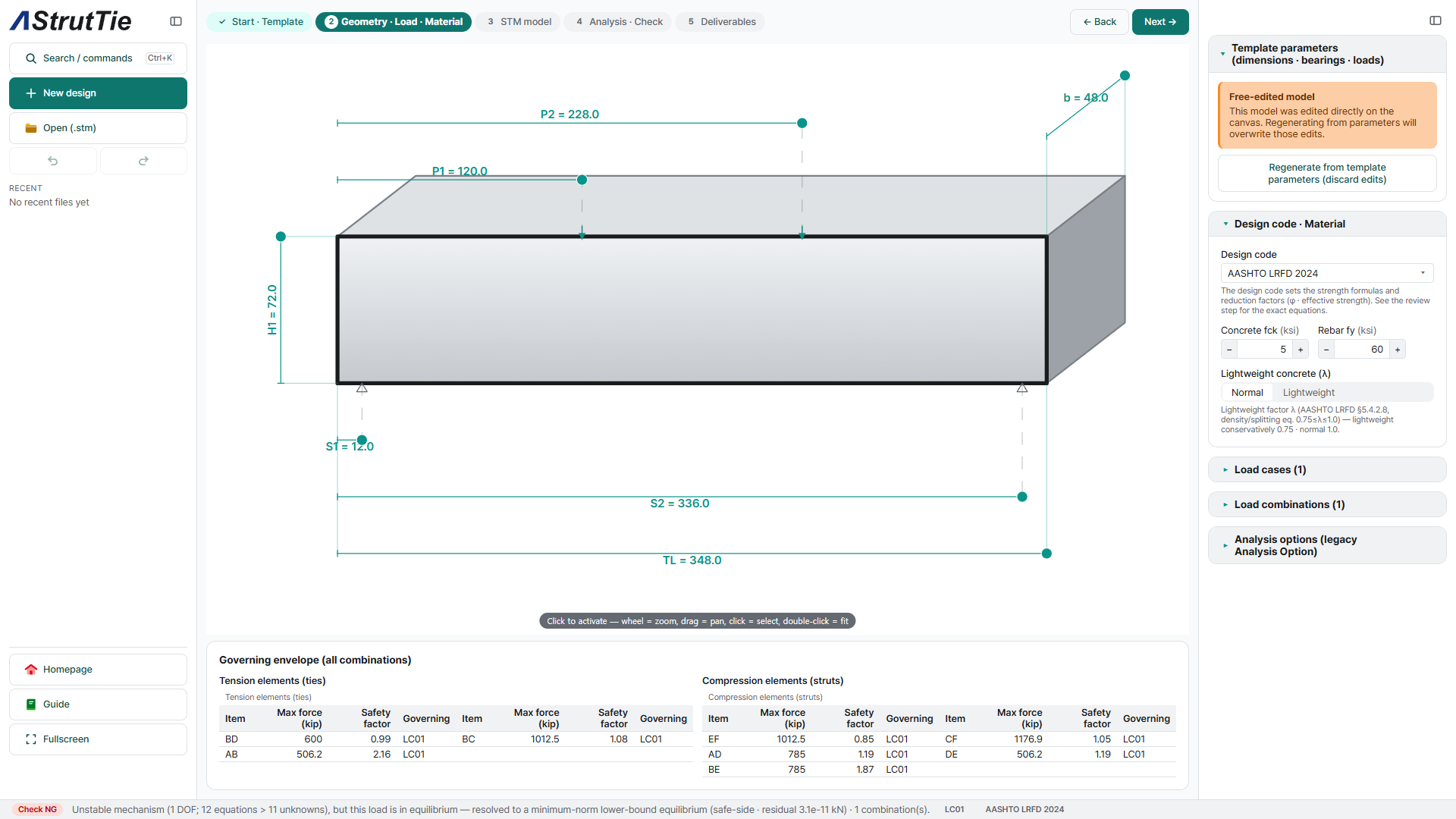
- Beam 72 in deep and 48 in wide · 27 ft between bearings · 1 ft overhang at each end
- Two loads of 600 kip (Strength I; 400 kip at service) at 108 in (1.5h) from the bearings
- Bearing plates 14 × 48 in at the loads and supports — the source's final size, after it lengthened them from 12 in
The problem
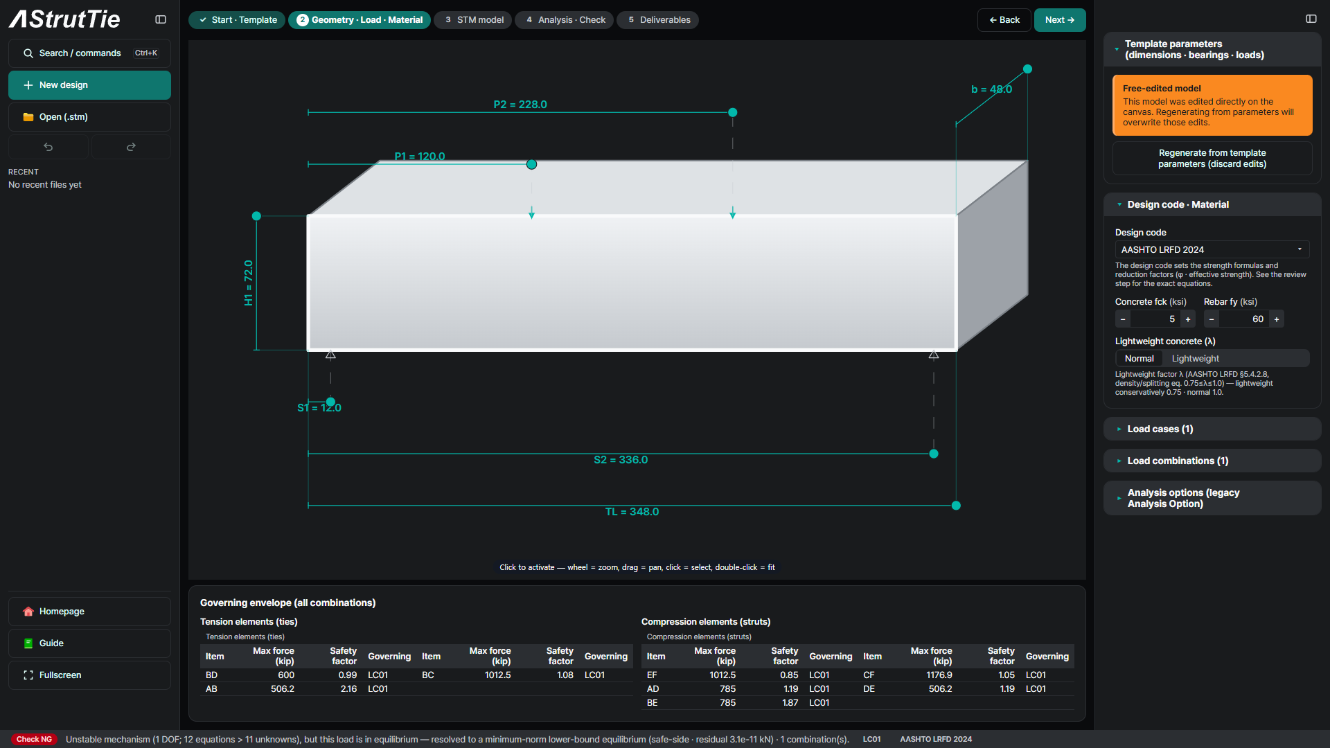
Two 600 kip loads sit 108 in from the bearings, a shear span of 1.5 times the depth, so the whole beam is a D-region. The source compares it to a straddle bent over a skewed roadway. The deep-beam template takes the length, depth, width, bearing and load positions and plate sizes directly — in kip and inch, as in the source.
Build the model — the FHWA truss
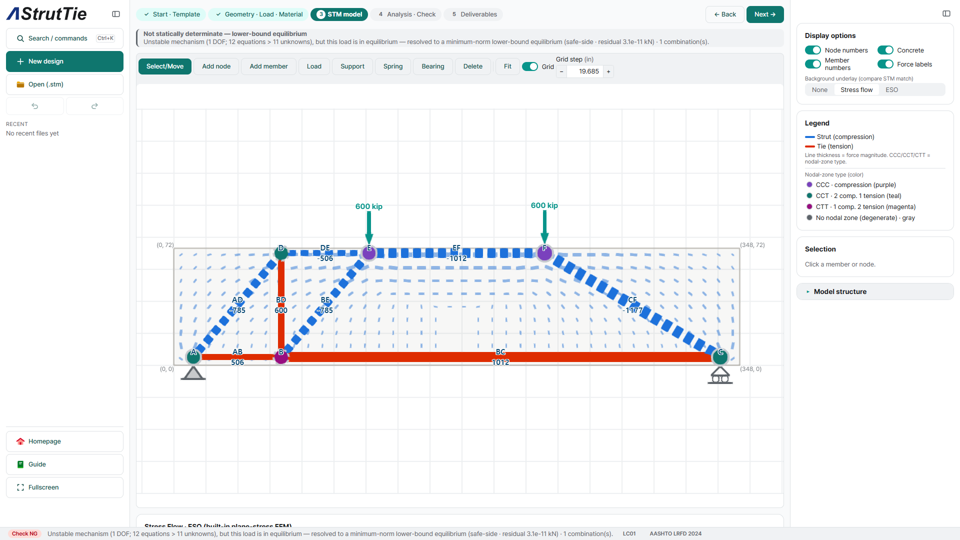
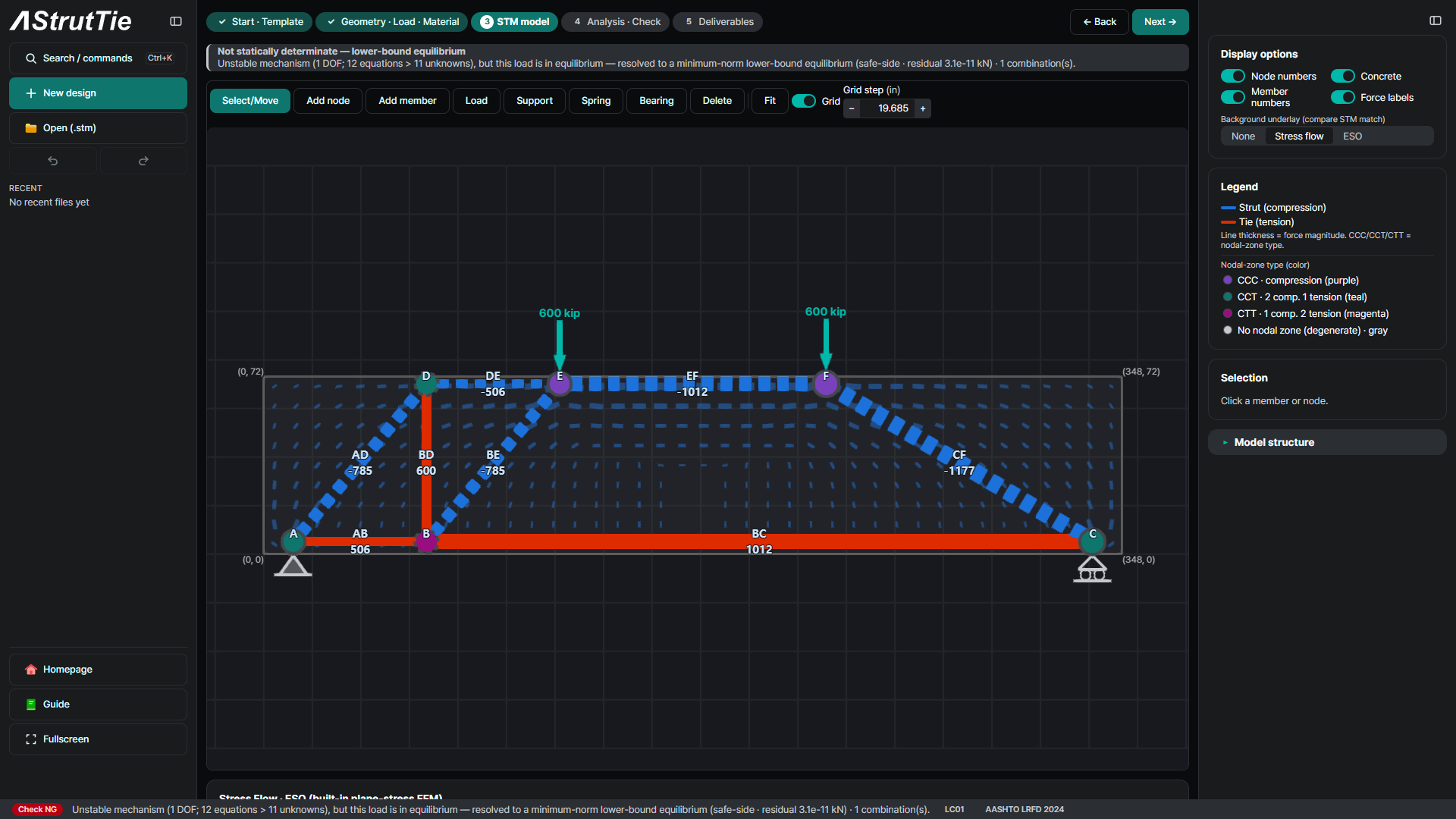
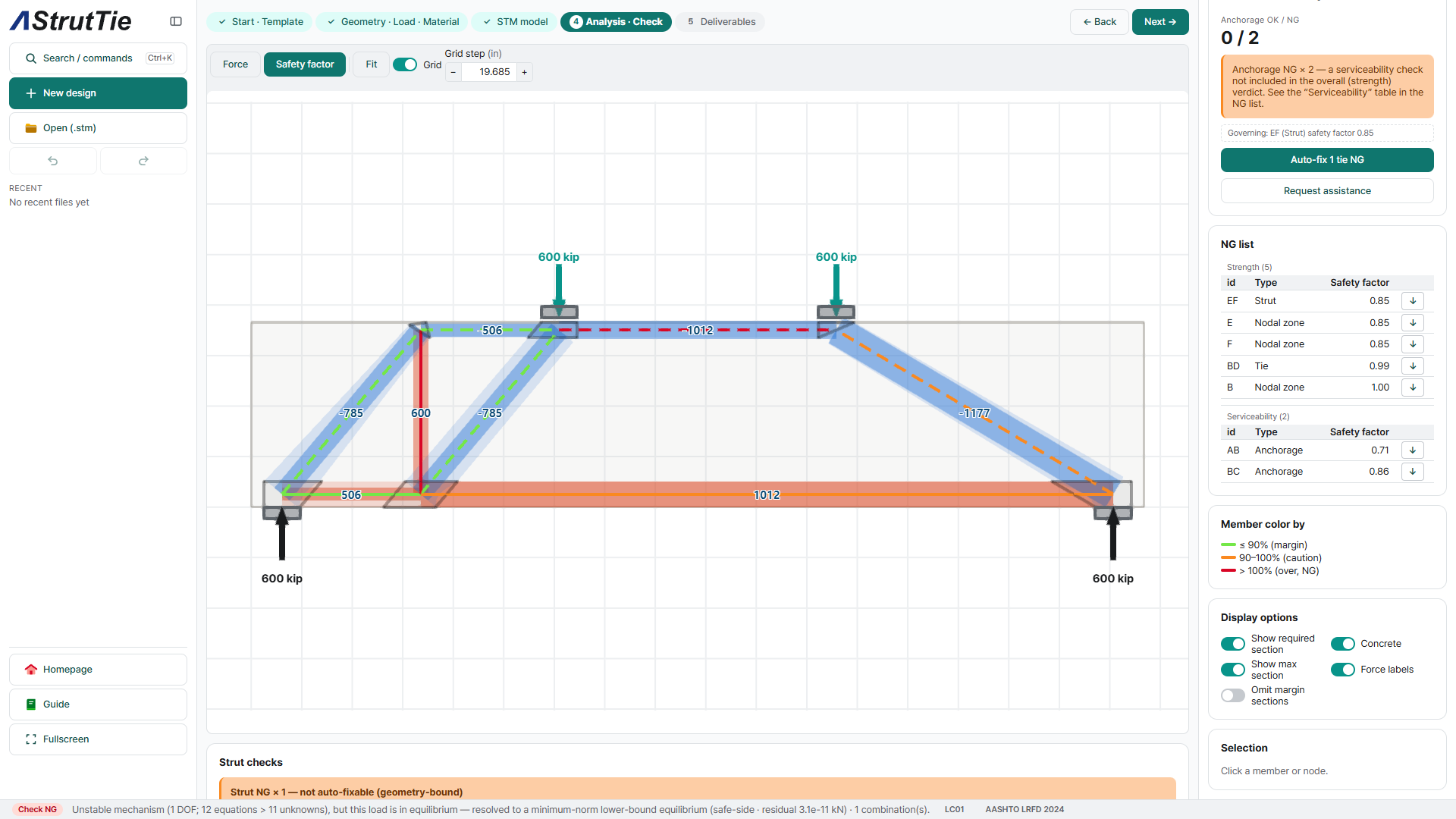
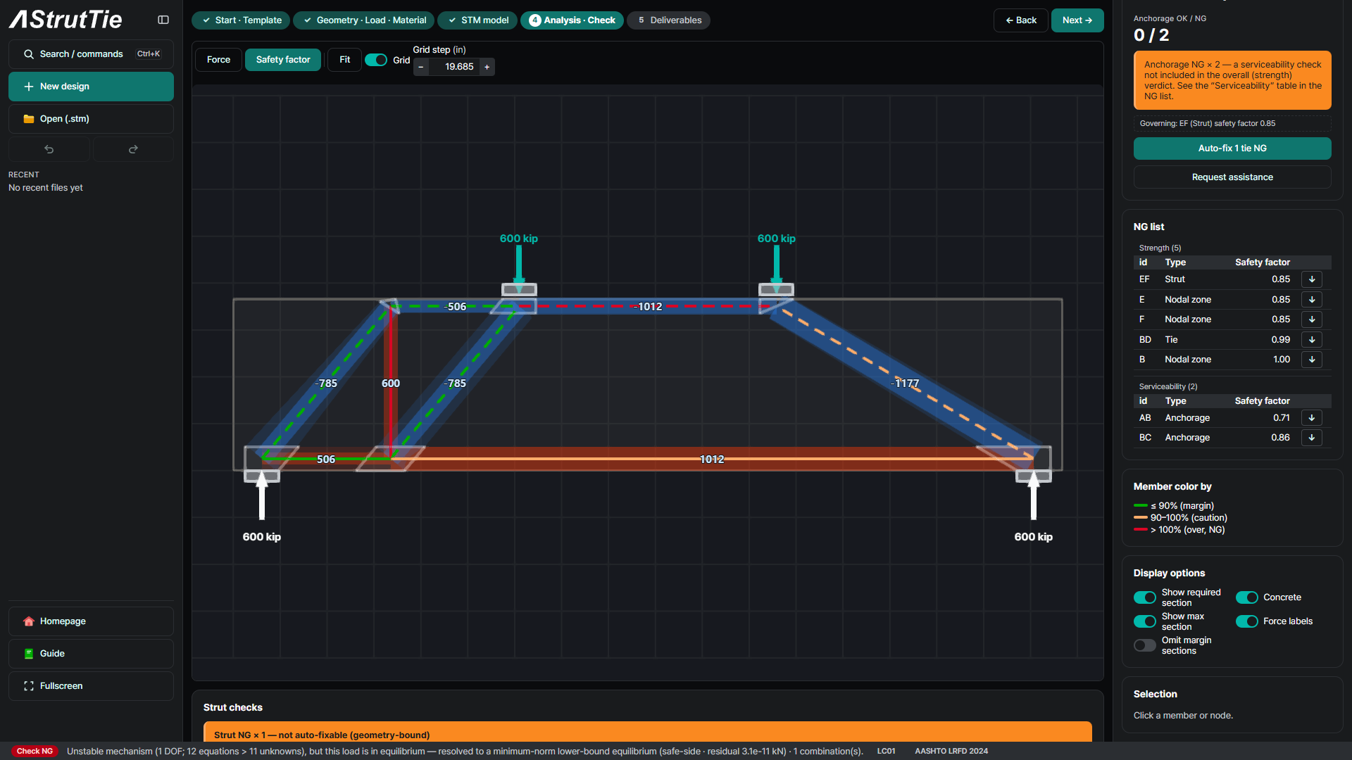
The source puts the top chord at mid-depth of an assumed 6 in compression block, 3 in below the top, and the tie 5 in above the bottom, so the truss is 64 in deep. To show both layouts, it carries the left load to its bearing through two panels, with a vertical tie BD at mid-shear-span, and the right load through one direct strut CF. The template places its intermediate station at the same half shear span, 54 in from the bearing; its extra diagonals were removed so that each half matches the source. The right half is a mechanism on its own. The source notes this is acceptable in STM, and the app reports it (one degree of freedom) and solves the load case as a lower-bound equilibrium. The forces are AB 506.3 · BC 1,012.5 · BD 600 · AD −785 · BE −785 · CF −1,176.9 · DE −506.2 · EF −1,012.5 kip, the source's Table 1-1 to within its rounding.
Analyze & check — every member, every node
9 of 14 strength checks pass. The five that do not come from three places: the top strut EF and its two CCC nodes E and F — the deficiency the source also finds — the vertical tie BD, and node B. Anchorage is reported separately from the strength verdict, and both ends of the bottom tie fail it under the 2024 development equation. Steps ④–⑦ go through each.
Tie check — required reinforcement
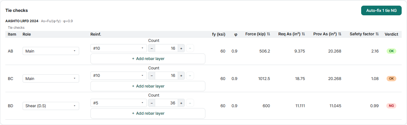
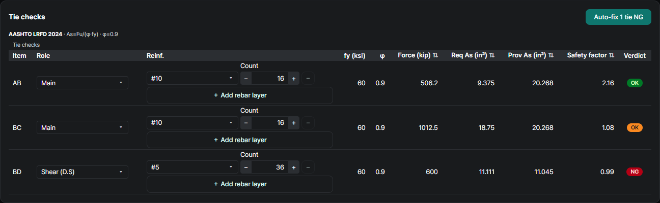
AASHTO LRFD 2024The bottom tie BC carries 1,012.5 kip and needs 18.75 in²; 16-#10 in two layers give 20.27 in² (safety factor 1.08), the same margin as the source's φPn = 1,097 kip. The vertical tie BD carries 600 kip and needs 11.11 in², as in the source. Nine sets of two #5 closed stirrups — 36 legs over the 48 in available length — give the source 11.16 in², just enough. The app takes a bar's area from its nominal diameter, π·d²/4 = 0.307 in² for #5, 1% below the ASTM nominal 0.31 in², so the same 36 legs give 11.05 in² and BD shows a safety factor of 0.99. The difference is the area convention, not the design.
Strut check — effective strength & width
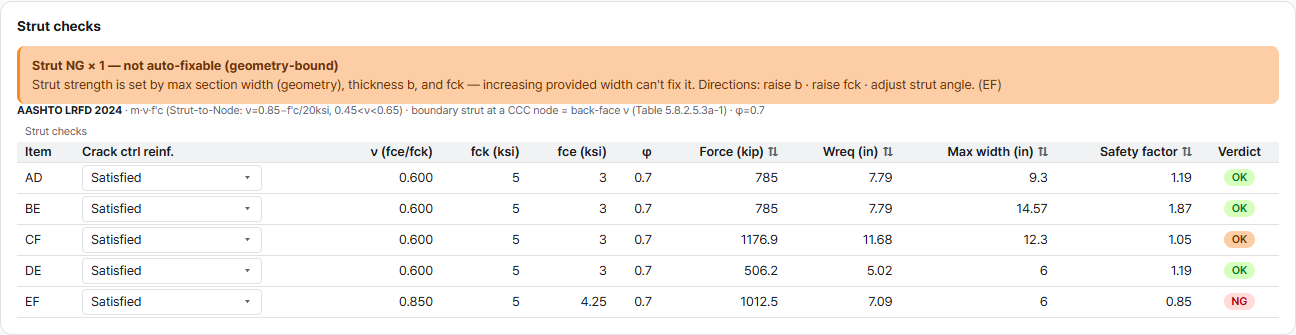
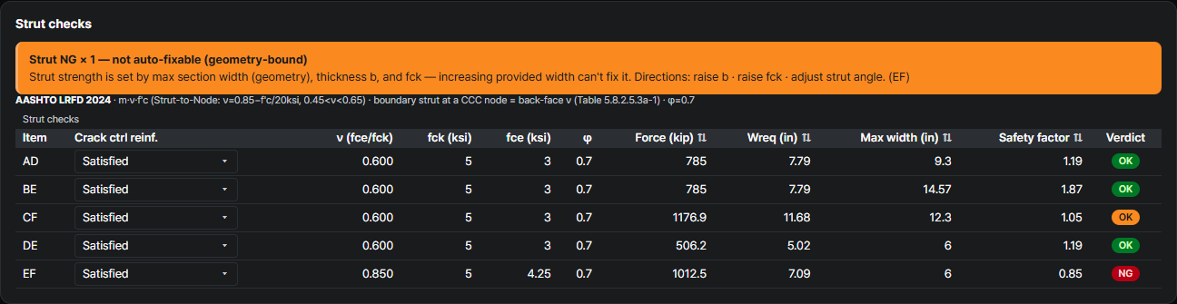
AASHTO LRFD 2024 Table 5.8.2.5.3a-1Under AASHTO LRFD a strut is checked where it meets a node. On a strut-to-node interface ν = 0.85 − f′c/20 ksi = 0.60, so fce = 3.0 ksi with φ = 0.70. CF needs 11.68 in and has 12.30 in at node F (safety factor 1.05) — the source's 1,239 against 1,177 kip after it lengthened the plates from 12 to 14 in. With 12 in plates the app gives 0.97, the source's 1,138 < 1,177 kip. The top strut EF runs between two CCC nodes and bears on their back faces, where ν = 0.85. It needs 7.09 in, and the 6 in compression block leaves 6 in: a safety factor of 0.85, the source's 856 < 1,013 kip. The source makes up the difference with six #8 bars in the top strut (§5.6.4.4, 4.74 ≥ 4.67 in²). The app does not model strut reinforcement, so the NG stays.
Nodal-zone check — by face and node type
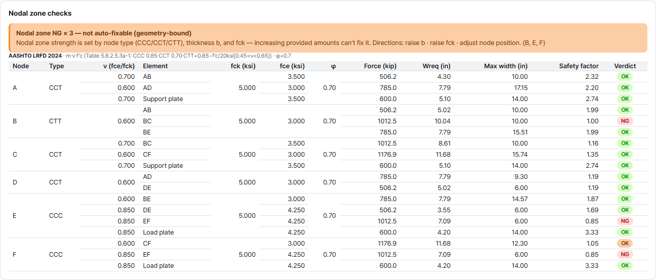
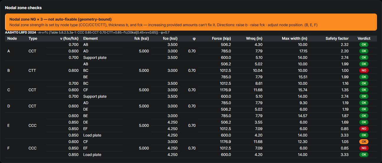
AASHTO LRFD 2024 Table 5.8.2.5.3a-1ν by face, for f′c = 5 ksi. At node C the bearing face needs 5.10 of 14 in (2.74) and the strut interface 11.68 of 15.74 in (1.35); the source's first check, with 12 in plates, has 14.7 in and 1,482 kip. The app also checks the back face of the bonded #10 tie at C (1.16), which AASHTO §5.8.2.5.3b does not require. Nodes E and F are governed by EF's back face (0.85, step ⑤); their bearing faces have 3.33. Node B, at the lower end of the vertical tie, is a smeared node the source does not check. The app checks every node of a 2D model, and there the back face of tie BC needs 10.04 of 10.00 in, a safety factor of 0.996 listed as NG. Node A has 2.20 and node D 1.19.
| Face | CCC | CCT | CTT |
|---|---|---|---|
| Bearing · back face | 0.85 | 0.70 | 0.60 |
| Strut-to-node interface | 0.60 | 0.60 | 0.60 |
Anchorage check — the 2024 development equation
AASHTO LRFD 2024 §5.8.2.4.2 · §5.10.8.2.4aThe bottom tie ends in 90° hooks (#10, 2 in cover). The available length is the source's: at C, 8.4 in from the extended nodal zone to the plate, the 14 in plate and 5 in beyond it, less 2 in cover — 25.4 in; at A, where strut AD is steeper, 21.2 in. What changed is the required length. The source (8th edition) takes ℓdh = 38·db/60 · fy/√f′c = 21.6 in and reduces it by the excess-reinforcement factor 0.92 to 19.9 in. The 2024 development equation gives 29.7 in for the same hook, and the app does not apply the excess-reinforcement reduction — safety factors 0.86 at C and 0.71 at A. The source checks only C.


What changes from the source
AASHTO LRFD 8th ed. → 2024Same beam, same truss, same forces. Under the 2024 edition the app reaches the source's own conclusion at the top strut — 0.85 on the back face of the CCC node. The other differences have known causes: the bar-area convention (BD), two checks the app makes that the source does not (node B and the tie back face at C), the strut reinforcement the app does not model (EF), and the new development equation (anchorage).
| Check | FHWA (AASHTO LRFD 8th ed.) | This example — AASHTO LRFD 2024 | Why |
|---|---|---|---|
| Member forces (8) | AB 506 · BC 1,013 · CF −1,177 kip … | AB 506.3 · BC 1,012.5 · CF −1,176.9 kip … | Same truss and statics |
| Bottom tie BC, 16-#10 | φPn 1,097 ≥ 1,013 kip | 18.75 in² required, 20.27 provided (1.08) | Same φ = 0.90 |
| Vertical tie BD, 36 legs of #5 | 11.16 ≥ 11.11 in² | 11.05 in² (0.99) — NG | Bar area: ASTM nominal (source) vs π·d²/4 (app) |
| Strut CF at node F | 12 in plate: 1,138 < 1,177 kip → 14 in: 1,239 kip | 12 in: 0.97 → 14 in: 1.05 | Same ν = 0.60 and the same plate change |
| Top strut EF, back face of node F | 856 < 1,013 kip → six #8 bars added | 0.85 — NG | Strut reinforcement is outside the app's model |
| Node C | Bearing 1,411 kip · interface 1,482 kip (12 in plate) · back face not checked | Bearing 2.74 · interface 1.35 · tie back face 1.16 | The app checks the bonded-bar back face, which §5.8.2.5.3b exempts |
| Node B (smeared) | Not checked | 0.996 — NG | The app checks every node of a 2D model |
| Crack control reinforcement | 0.003·bw·s both ways: 4-#6 per ft · 2-#5 stirrups @ 8 in | Taken as provided, as in the source | ν uses the crack-controlled values; the amount is a hand check |
| Hooked #10 anchorage at C | 19.9 in required (λer 0.92) ≤ 25.4 in | 29.7 in required > 25.4 in (0.86) — NG | 2024 development equation; no excess-reinforcement reduction in the app |
These are the checks AStrutTie runs on every model — here against a free FHWA example anyone can download, with the forces matching the source and every difference traced to a clause, a convention or an edition. How we verify →
Try it on your own numbers
Open AStrutTie in your browser, sign in with your email and start from the same template. The Free plan needs no installation and no card.