A worked example — an abutment footing on ground
An abutment footing is the least symmetric member in this set: the wall pushes down and sideways off-center, the heel carries the backfill, and the ground answers with a pressure that is anything but uniform. This is Example 3.2 of the AStrutTie 2020 Technical Book, opened as a built-in example in the current AStrutTie with the book's own strut-and-tie model and checked under ACI 318-25: every check value the book prints comes out the same, and the one tie the book leaves to the wall design is shown as the app reports it.
Problem data, the model and the check values are from the AStrutTie 2020 Technical Book, Example 03-3.2 (abutment, spread foundation, ACI 318-19). The example ships with the app; every check below was run in the current AStrutTie under ACI 318-25.
Given
- f′c = 24 MPa · fy = 400 MPa · φ = 0.75
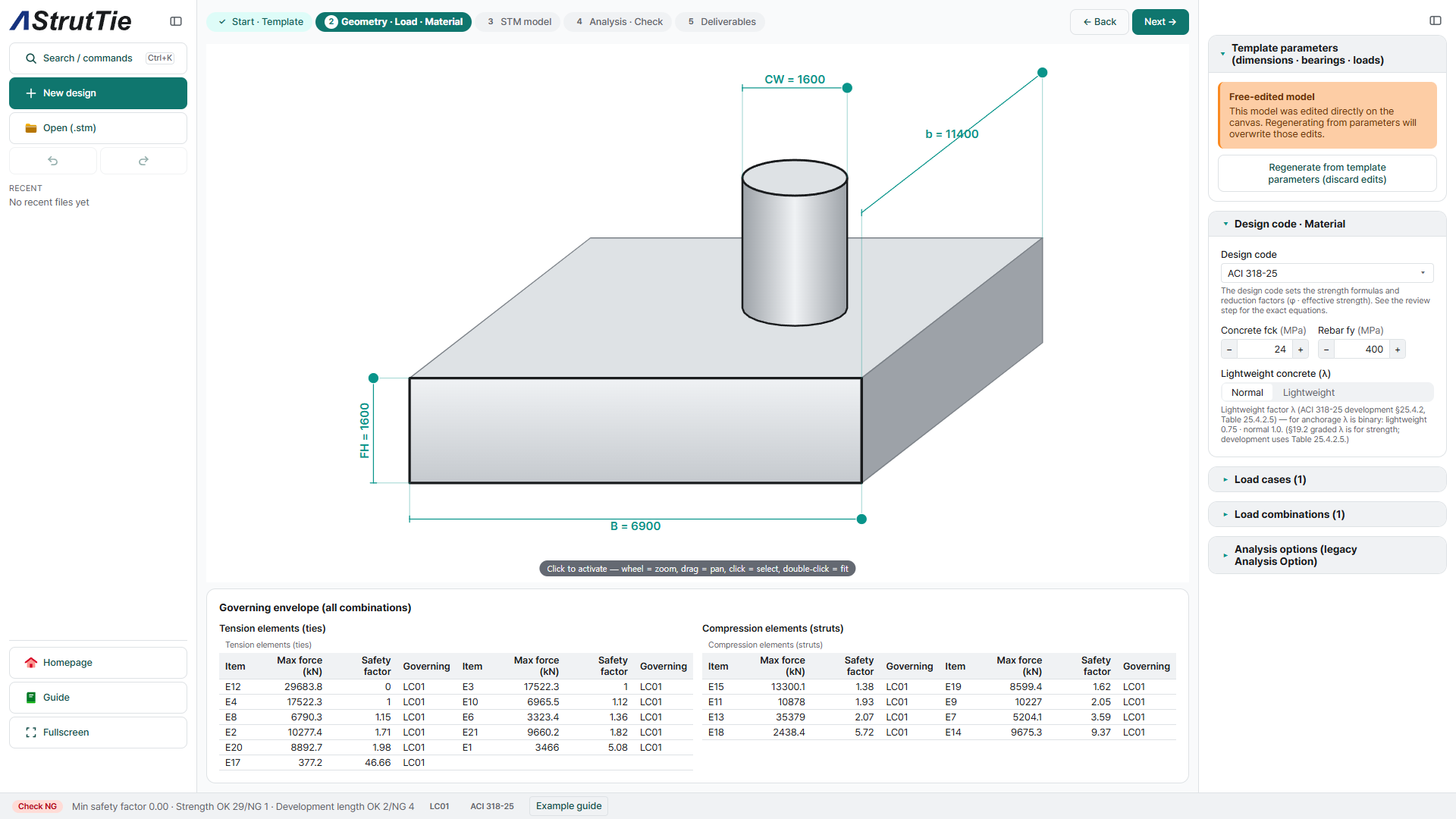
- Footing 6,900 × 11,400 mm, 1,600 mm thick · wall 1,600 mm thick · heel 3,700 mm, toe 1,600 mm
- Wall (case W): V = 13,460 kN · H = 3,590 kN · M = 42,700 kN·m · backfill on the heel (case D): w₁ = 1,300 kN/m, w₂ = 650 kN/m · LC01 = 1.00 W + 1.00 D
- Ground springs 30,000 kN/m² vertical and 10,000 kN/m² horizontal · bars top and bottom 91-#9 · shear bars #6, 22 legs @ 300 mm vertical and 2 bars @ 300 mm horizontal
The problem
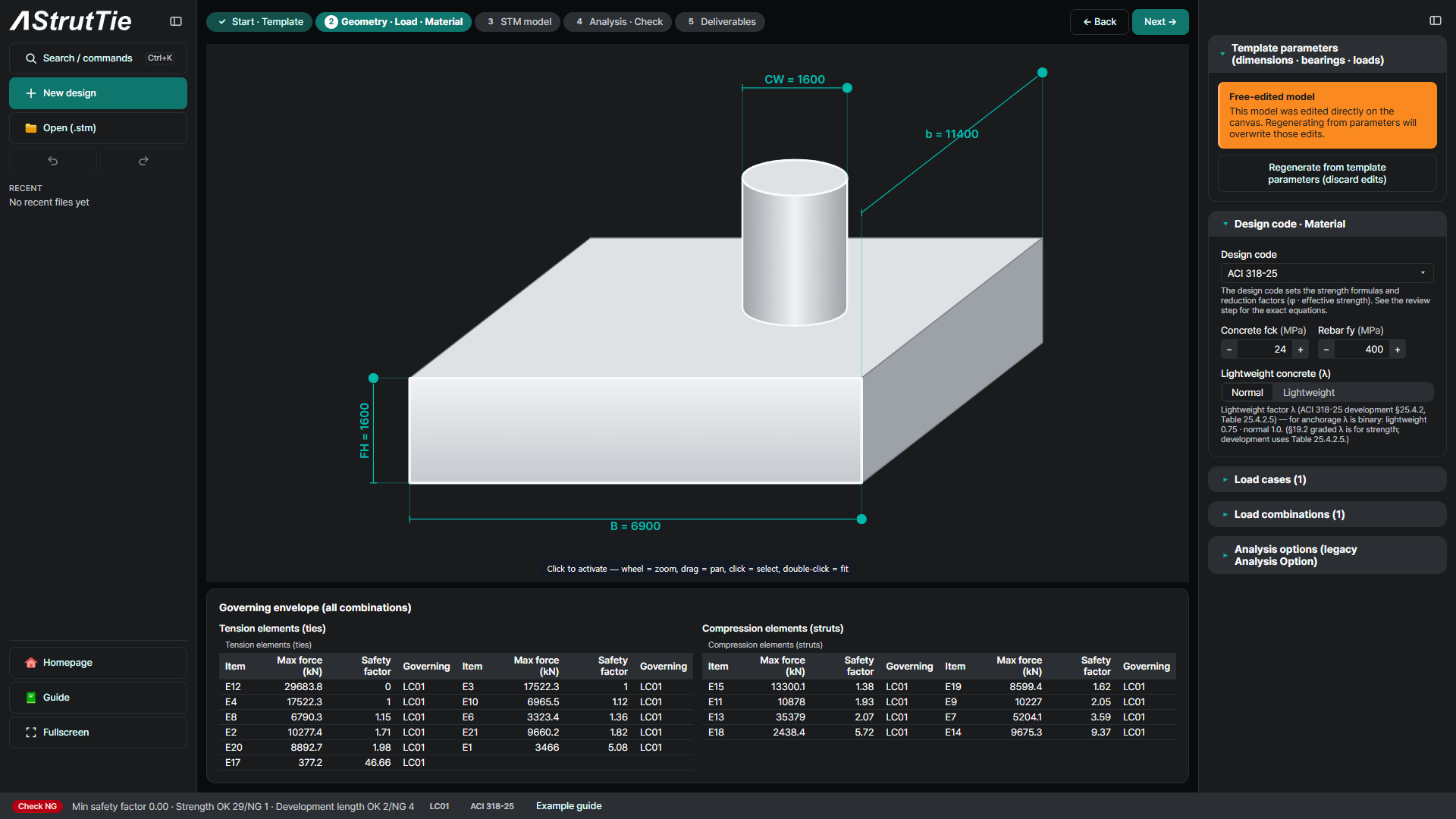
The wall stands 3,700 mm from the heel end and brings 13,460 kN down, 3,590 kN sideways and a moment of 42,700 kN·m. The backfill bears down on the heel, and the ground answers through springs, vertically and horizontally. The Technical Book example opens in AStrutTie with its dimensions, loads, material and bars already entered. The 3D preview draws the wall as a round 1,600 mm column; the check itself is a 2D section through the footing, with the full 11,400 mm width as its thickness.
Build the model — the book's own truss
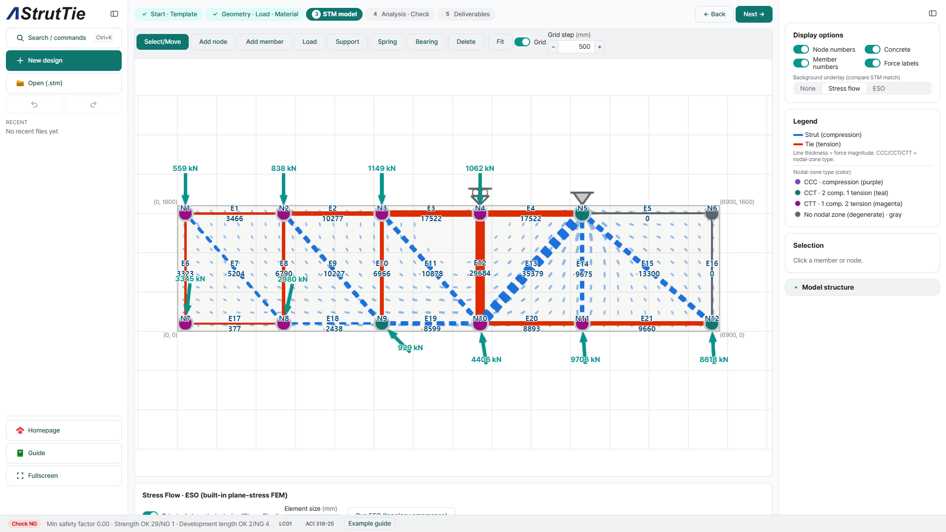
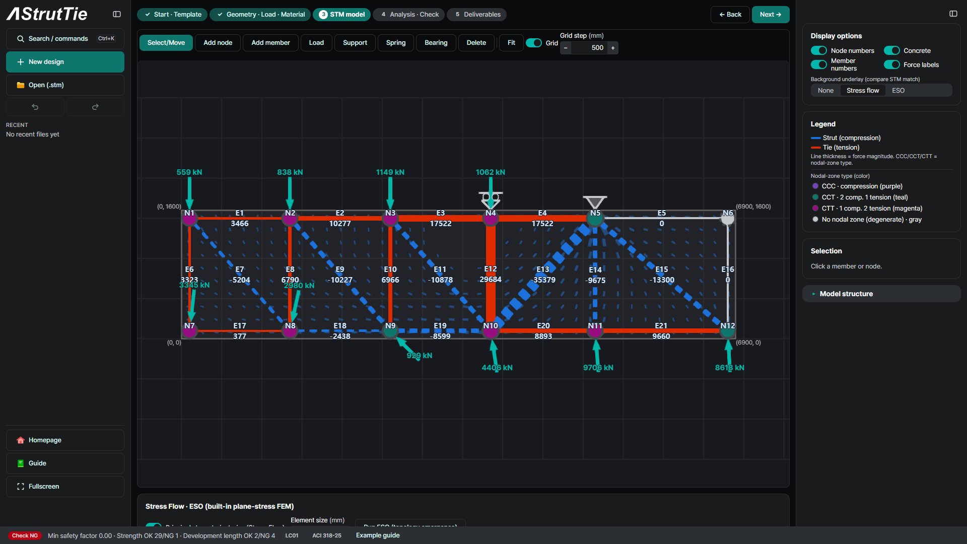
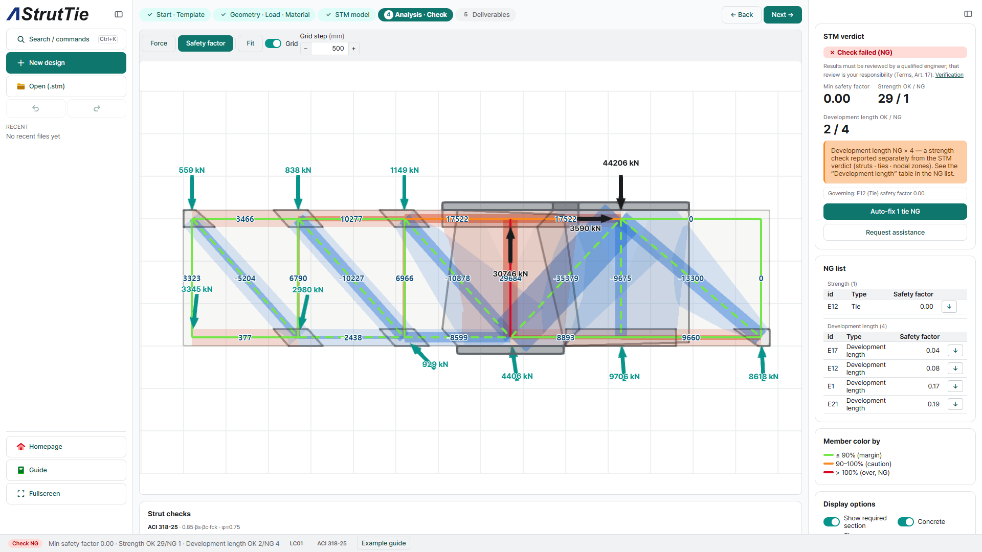
This example does not start from the template. It opens with the Technical Book's final model, 12 nodes and 21 elements, statically determinate. The wall is the support, a roller at N4 and a pin at N5, and the backfill and the ground come in as loads on the top and bottom nodes. The book prints no table of those loads, so the example back-calculates them from the book's member forces. All 21 member forces then agree with the book — E13 −35,379.0 kN, the largest compression, and E3 +17,522.3 kN, the largest top-chord tension — but that agreement is a reproduction, not a check. The checks in ④–⑥ are the independent part.
Analyze & check — every member, every node
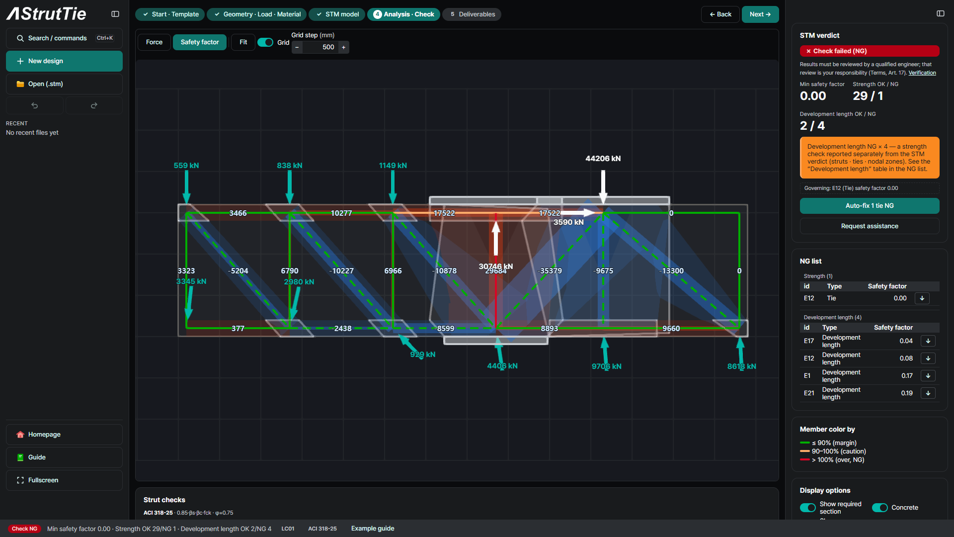
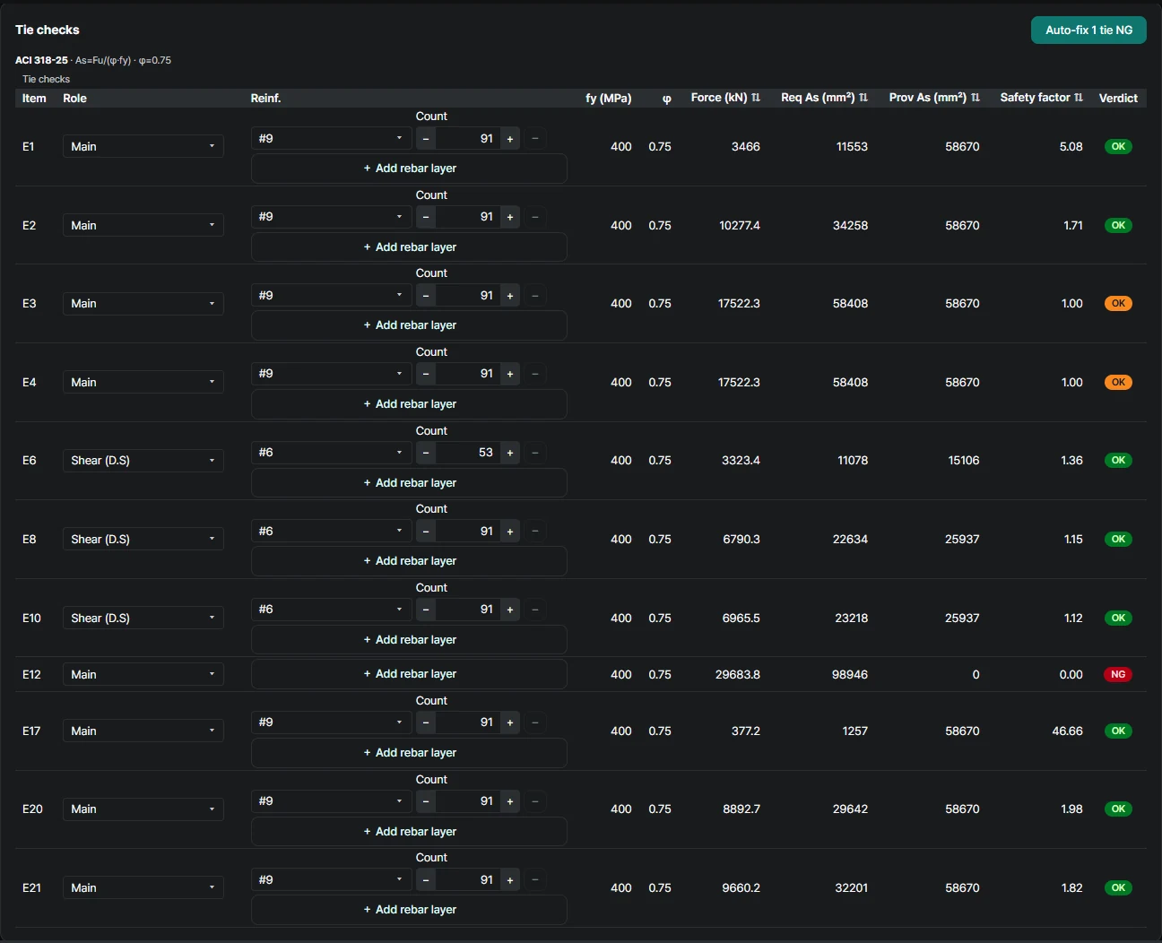
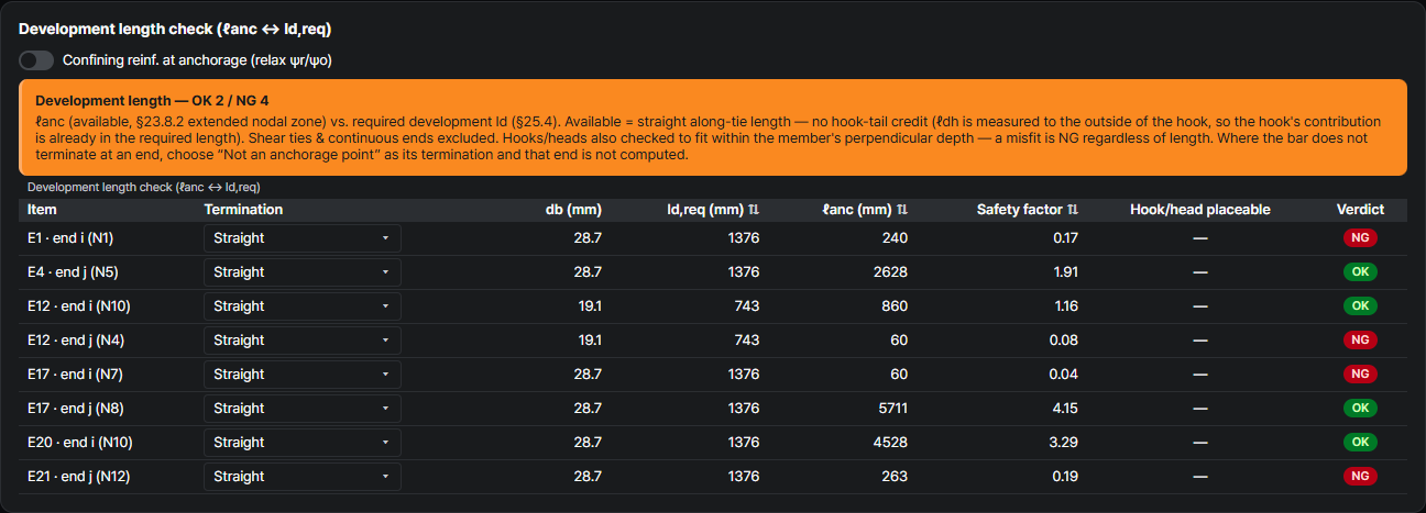
29 of 30 strength checks pass. The one that fails is E12, the vertical tie at the heel-side face of the wall: it stands for the wall's main bars anchored in the footing, which the book leaves out of its footing check tables. The example enters no bars for it, so the tie table shows 0 mm² provided against the 98,946 mm² it needs, and the check fails with a safety factor of 0.00. The NG is shown as the app reports it; entering the wall bars as E12's rebar gives it a verdict. Anchorage is reported separately from the strength verdict, and four tie ends fail it; step ⑦ explains why.
Tie check — required reinforcement
ACI 318-25The top chord over the heel and the wall carries the most: 17,522.3 kN in E3 and E4, needing 58,408 mm² against the 58,670 mm² of 91-#9 — a safety factor of 1.00, the same 0.4% margin the book reports. At the toe, E21 carries 9,660.2 kN and needs 32,201 mm² (1.82). The vertical ties E6, E8 and E10 are the shear bars; the most loaded, E10, carries 6,965.5 kN on 91 bars of #6, 25,937 mm² (1.12). The book's T3 and T21 checks come out the same in the app's comparison.

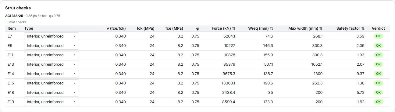
Strut check — effective strength & width
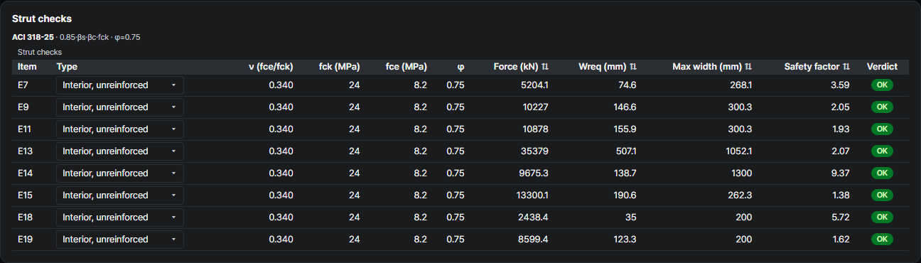
ACI 318-25 §23.4 · §23.5The vertical shear bars, 22 legs of #6 at 300 mm across the 11,400 mm width, give ρ ≈ 0.0018, below the 0.0025 per direction that §23.5 asks for βs = 0.75. Every strut is therefore taken as βs = 0.40, as in the Technical Book: fce = 8.16 MPa. The largest strut, E13, runs under the wall from N10 up to the support N5: 35,379.0 kN needs 507.1 mm of the 1,052.1 mm available (2.07). The tightest is E15, from N5 down to the toe end: 13,300.1 kN needs 190.6 of 262.3 mm (1.38). Both match the book's S13 and S15.
Nodal-zone check — by node type
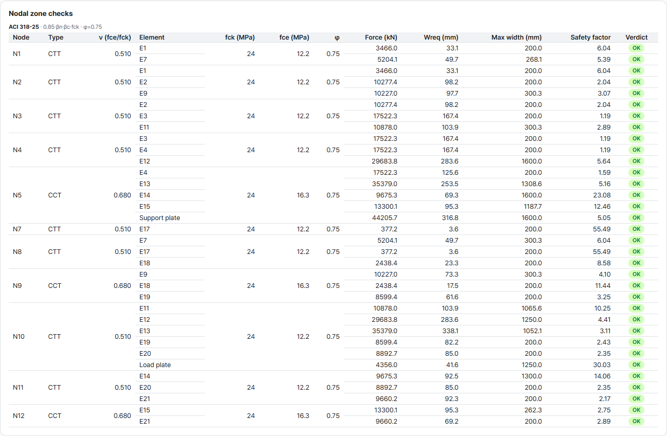
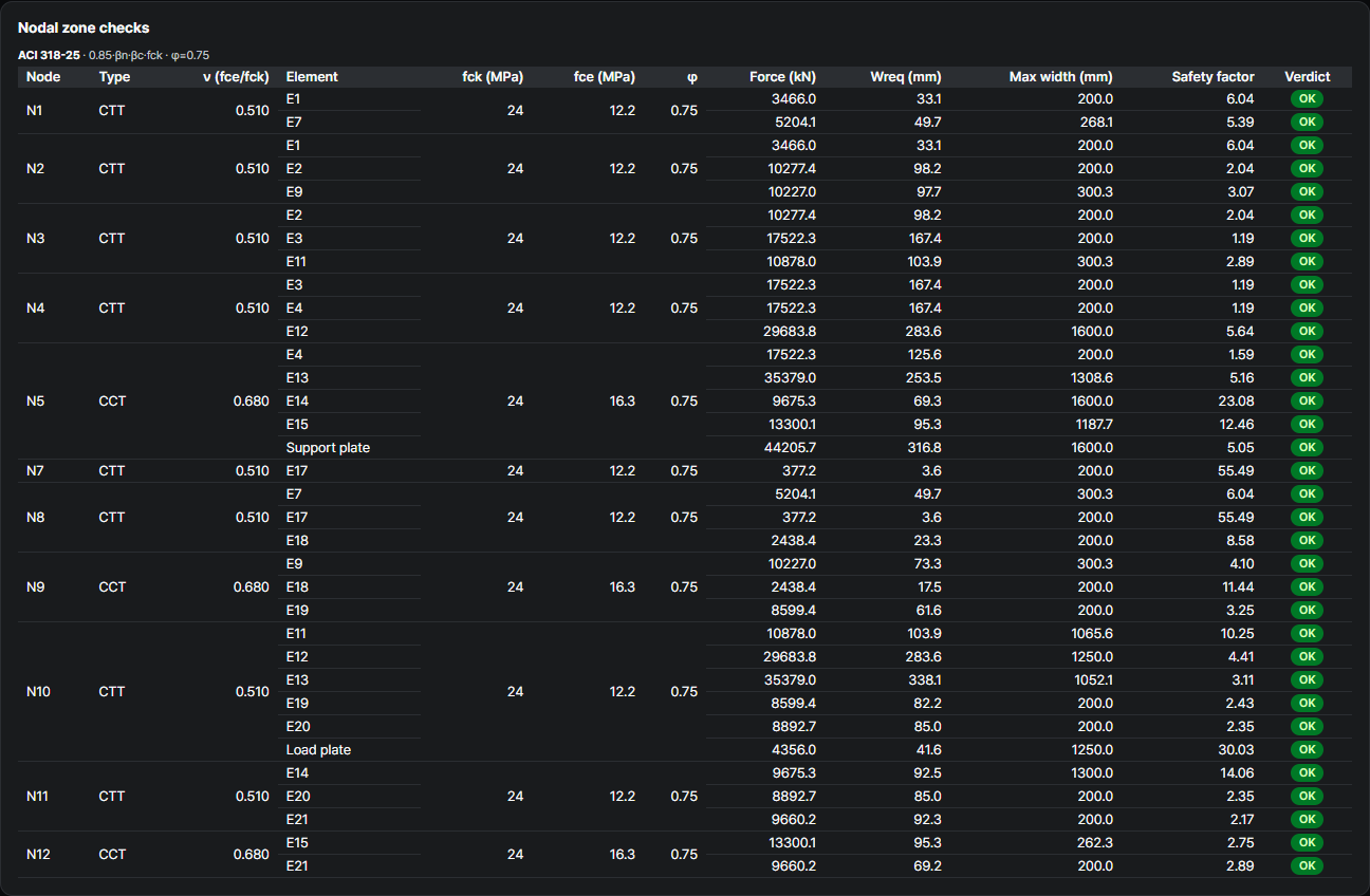
ACI 318-25The tightest nodes are N3 and N4 on the top chord, where the 17,522.3 kN of E3 needs 167.4 of 200 mm on the tie face (1.19). The support node N5, where the wall bears down, has 1.59; at N4 the wall pulls up instead, so that plate carries no bearing compression and has no face to check. The book's check of node N3, face C-11 with 10,878.0 kN needing 103.9 mm, is reproduced exactly in the app's comparison.
| Node | βn | fce (MPa) |
|---|---|---|
| CCC | 1.0 | 20.4 |
| CCT | 0.8 | 16.3 |
| CTT | 0.6 | 12.2 |
Development length check — bars that end near the edge
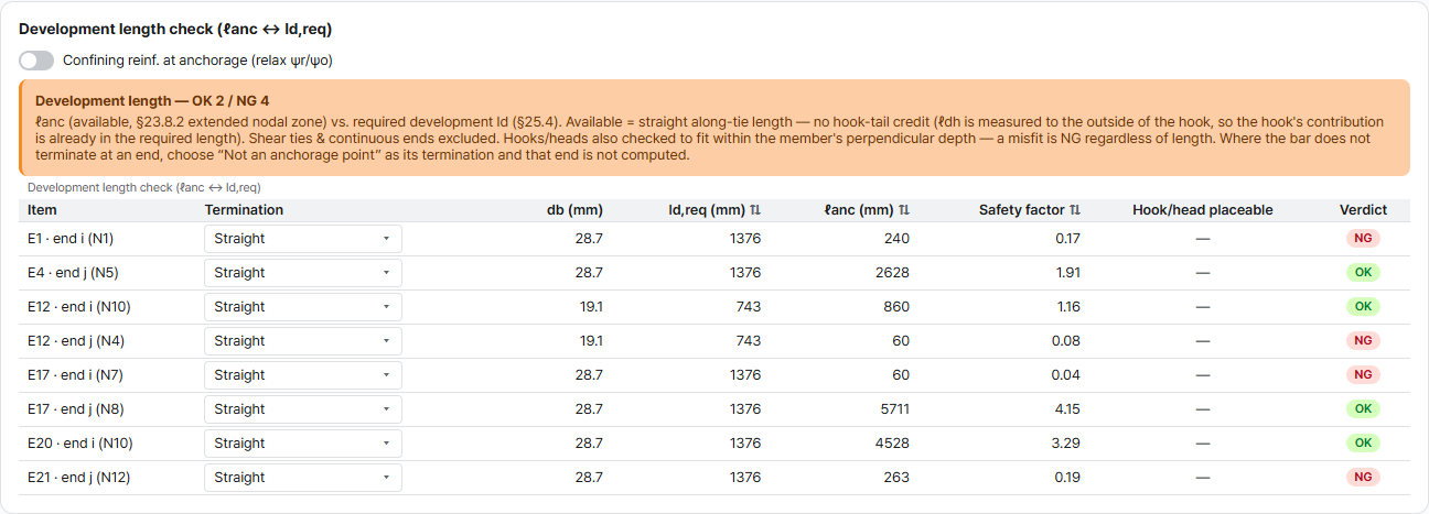
ACI 318-25 §23.8.2 · §25.4The end nodes sit 100 mm from the ends of the footing. A straight #9 bar needs ℓd = 1,376 mm, and the extended nodal zones leave 240 mm for the top bars at the heel end (E1) and 60 and 263 mm for the bottom bars at the heel and toe ends (E17, E21): safety factors 0.17, 0.04 and 0.19. A 90° hook brings the requirement down to 902 mm, still more than is available. E12, the wall tie of step ③, also fails at its top end: 60 mm against 743 mm for the default D19 (0.08). The NG is shown as the app reports it. The Technical Book's check tables for this example do not cover anchorage.
What changes from the Technical Book
ACI 318-19 → ACI 318-25Same footing, same loads, same bars, and the book's own model. The strength equations and φ are the same in both editions, so every check value the book prints comes out the same. What the app adds is two checks the book's tables leave out: the wall tie E12, which the book leaves to the wall design, and the anchorage of every tie end.
| Check | Technical Book (2020 · ACI 318-19) | This example — ACI 318-25 | Why |
|---|---|---|---|
| Values that must match (8) | T3 17,522.27 kN → 58,407.55 mm² · S13 35,379.0 kN → 507.1 mm · N3 C-11 10,878.0 kN → 103.9 mm … | 8 of 8 the same | Same strength equations and φ |
| Model | Final model — 12 nodes · 21 elements | The same model — 12 nodes · 21 members · statically determinate | The example opens with the book's model |
| Member forces | E3 +17,522.3 · E13 −35,379.0 · E21 +9,660.2 kN | 21 of 21 the same | Loads back-calculated from the book's forces — a reproduction, not a check |
| Top bars, 91-#9 | As,used 58,670.22 mm² · T3 needs 58,407.55 mm² | 58,670 mm² · 1.00 at E3 and E4 | Same bars — the tightest tie in both |
| Shear reinforcement | Tie10 6,965.52 kN · weff 1,250.0 mm · φFn 7,838.2 kN | E10 6,965.5 kN · 91-#6, 25,937 mm² (1.12) | Same bars; the app counts whole bars across weff |
| Wall tie E12 | +29,683.8 kN · not in the footing check tables | No bars entered — 0 mm² provided against 98,946 mm²: NG (0.00) | The app checks every tie; the wall bars belong to the wall design |
| βs of the struts | 0.40 | 0.40 | #6 gives ρ ≈ 0.0018 < 0.0025 (§23.5) |
| Anchorage of the end bars | Not in the check tables | 240 · 60 · 263 mm available < 1,376 mm required — NG · a 90° hook needs 902 mm | The app checks every tie end |
These are the checks AStrutTie runs on every model — here on an example from the AStrutTie 2020 Technical Book, opened in the current app with the book's own model, with every check value the book prints reproduced and every difference traced to what the book's tables leave out. How we verify →
Try it on your own numbers
Open AStrutTie in your browser, sign in with your email and start from the same template. The Free plan needs no installation and no card.