A worked example — a pile-cap footing D-region
A pile cap turns a single column's load a sharp corner and spreads it onto a group of piles. That abrupt change is what makes it a D-region — beam theory no longer applies, so it is designed with a strut-and-tie model. Here is the workflow in AStrutTie on a one-column pile cap.
Based on the AStrutTie 2020 Technical Book, Example 2.1 (one-column pile foundation), run under ACI 318-25.
Given
- fck = 35 MPa (concrete)
- fy = 400 MPa (steel)
- φ = 0.75 (strength-reduction factor)
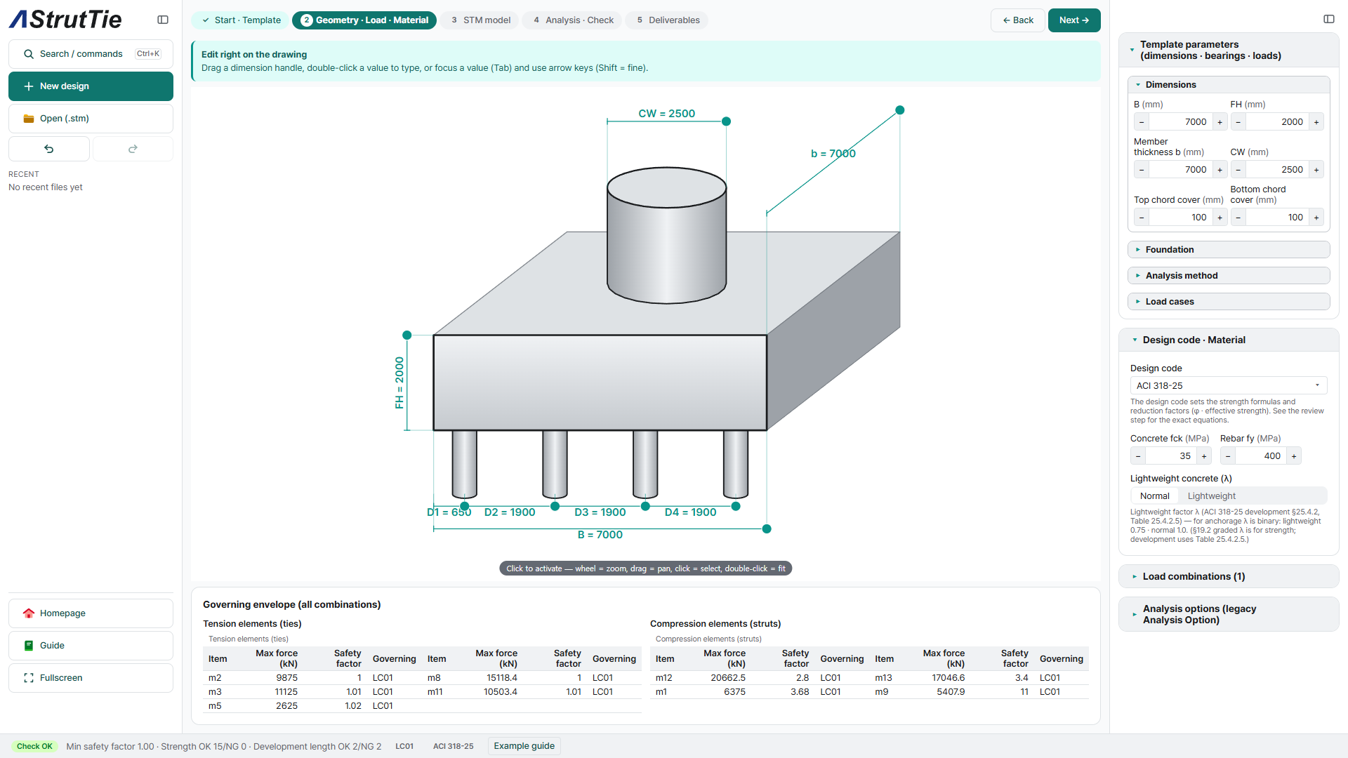
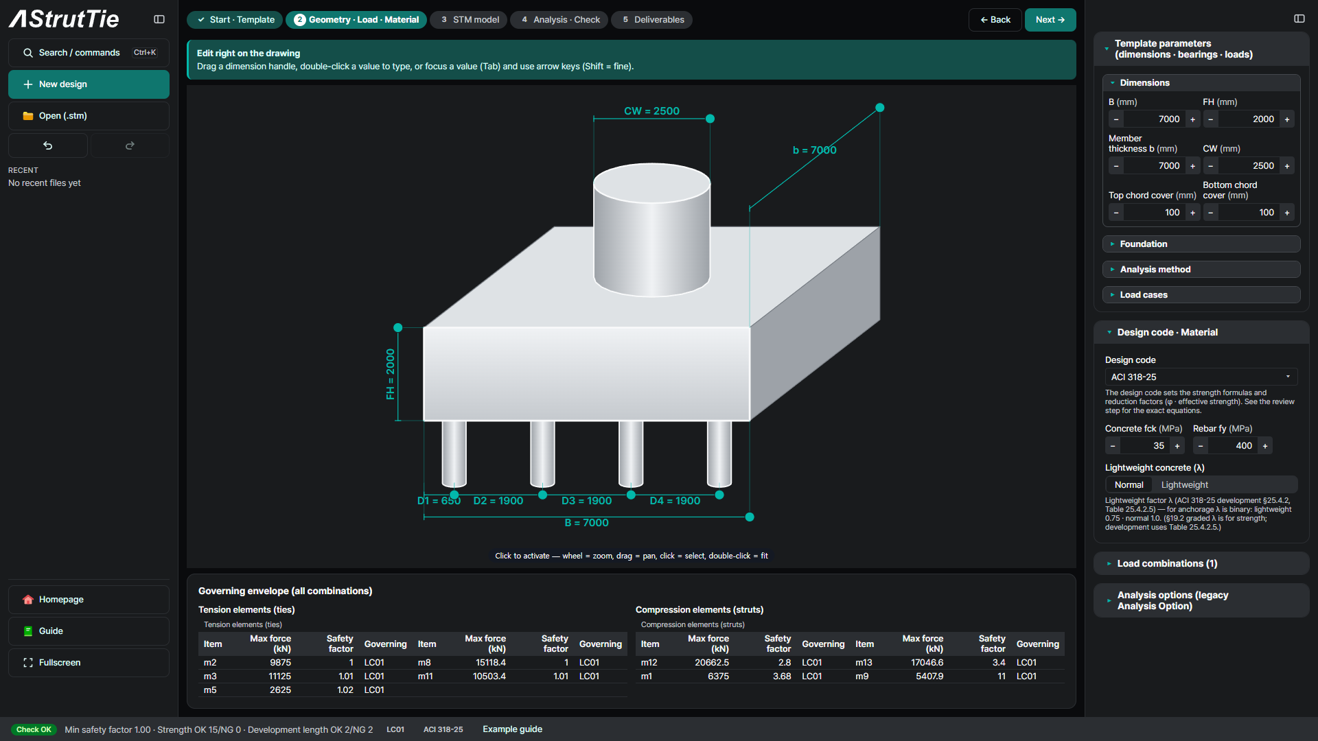
- Footing dimensions, pile layout & column load — entered in the template (see the drawing below)
The problem
A pile cap carries a column's load down to a group of piles. Its footing dimensions, pile layout and column load define the design — typed straight onto the drawing.
Build the model — template → strut-and-tie
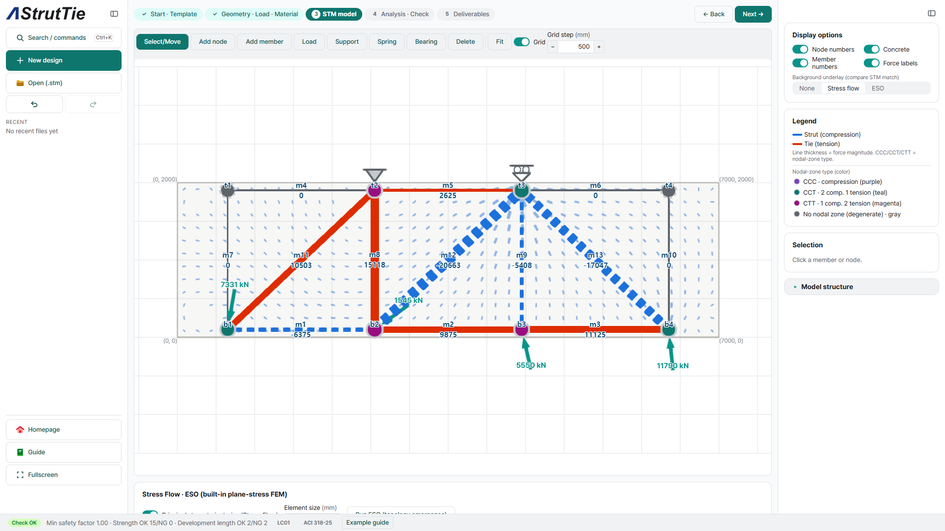
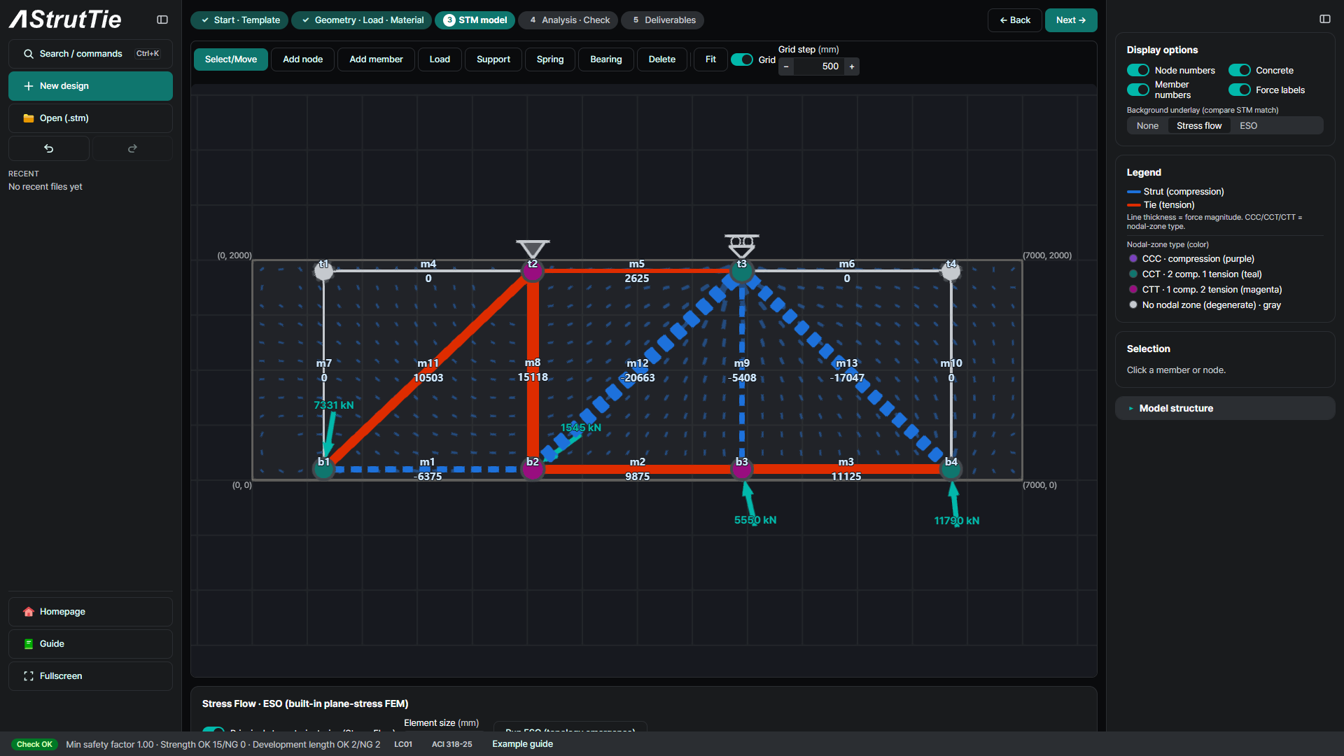
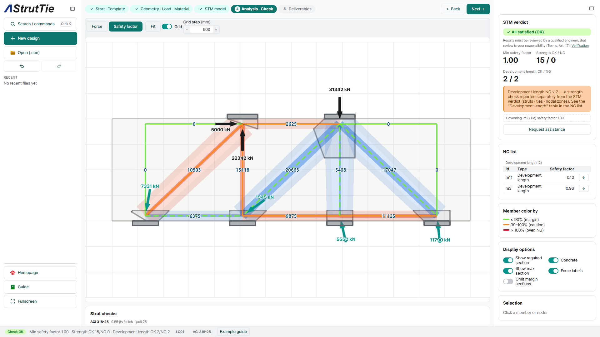
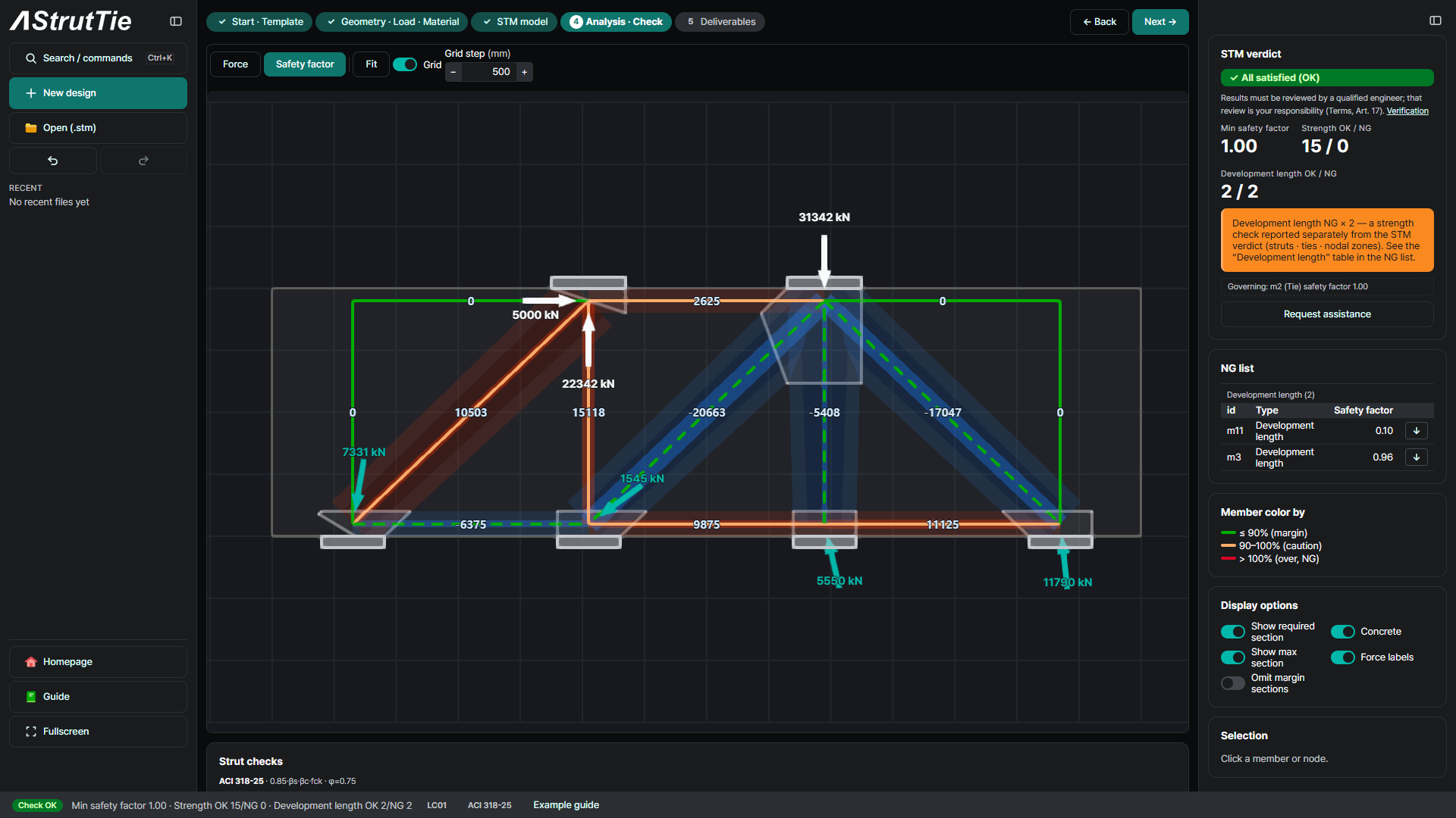
The pier-footing template builds a strut-and-tie model automatically: compression struts (dashed) fan from the column down to each pile, tension ties (solid) span between the pile heads, and nodal zones are typed CCC / CCT / CTT.
Analyze & check — every member, every combination
AStrutTie resolves the member forces and checks every member against the code — ties, struts, nodal zones and anchorage — in one pass.
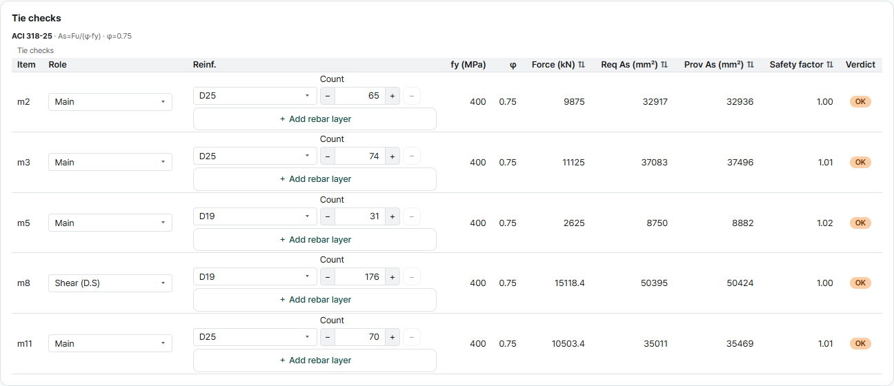
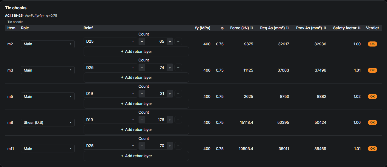
Tie check — required reinforcement
ACI 318-25Required steel As,req is compared with the provided bars (size × count). φ = 0.75, fy = 400 MPa.
Strut check — effective strength & width
ACI 318-25Effective strength depends on strut type — Boundary (fce = 0.85 fck = 29.8 MPa) or Interior, reinforced (0.637 fck = 22.3 MPa). The required width must fit the available width.


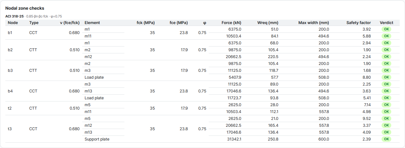
Nodal-zone check — by node type
ACI 318-25| Node | βn | fce (MPa) |
|---|---|---|
| CCC | 1.0 | 29.8 |
| CCT | 0.8 | 23.8 |
| CTT | 0.6 | 17.9 |
Development length check — anchorage at the node
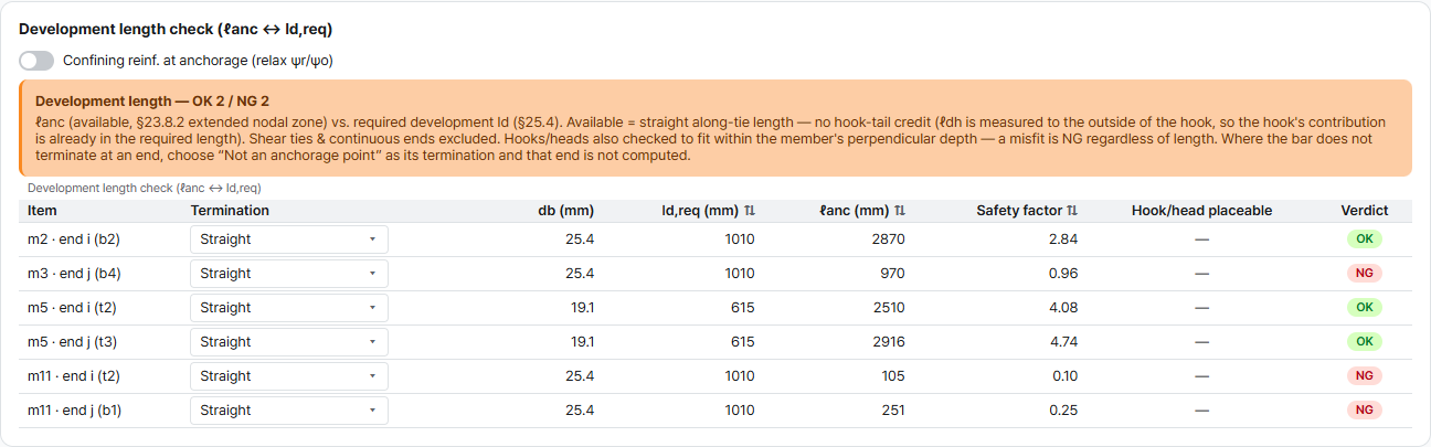
ACI 318-25 §23.8.2 · §25.4The tie must be anchored where it meets the pile nodes: the available anchorage ℓanc (§23.8.2, extended nodal zone) must reach the required development length ℓd (§25.4). Available = straight length along the tie — no hook-tail credit: ℓdh is measured to the outside of the hook, so the hook's contribution is already in the required length.
These are the same checks AStrutTie runs — the pile-cap load path, from column down to the piles, verified member by member. How we verify →
Try it on your own numbers
Open AStrutTie in your browser, sign in with your email and start from the same template. The Free plan needs no installation and no card.