A worked example — designing a pier-coping D-region
A pier coping is a classic D-region: beam theory does not apply, so it is designed with a strut-and-tie model. Here is the full workflow in AStrutTie — template → model → analysis → code checks — on a single-column pier coping.
Based on the AStrutTie 2020 Technical Book, Example 01 — the same case one of our verification fixtures is built from, run here under ACI 318-25.
Theory: Hammerhead pier caps — designing the cantilevers with strut-and-tie
Given
- fck = 24 MPa (concrete)
- fy = 400 MPa (steel)
- φ = 0.75 (strength-reduction factor)
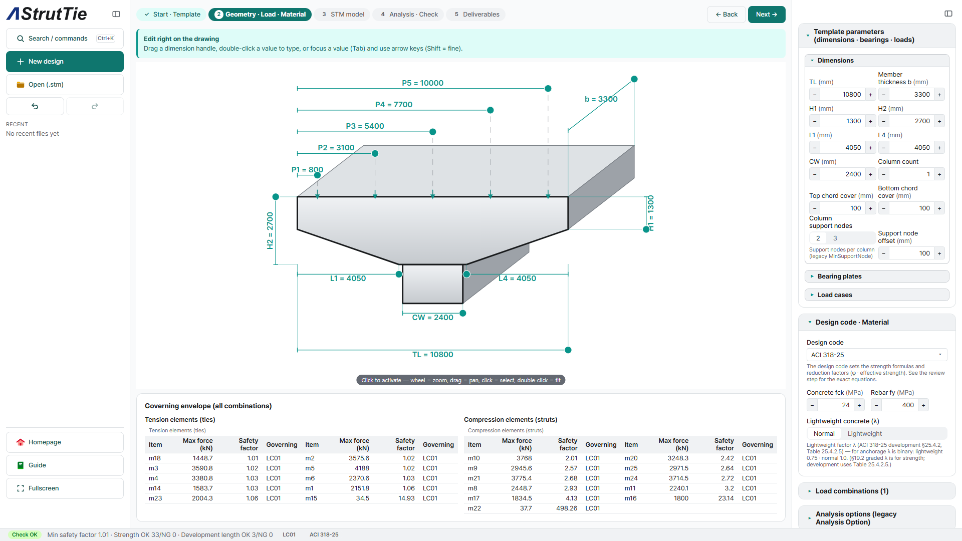
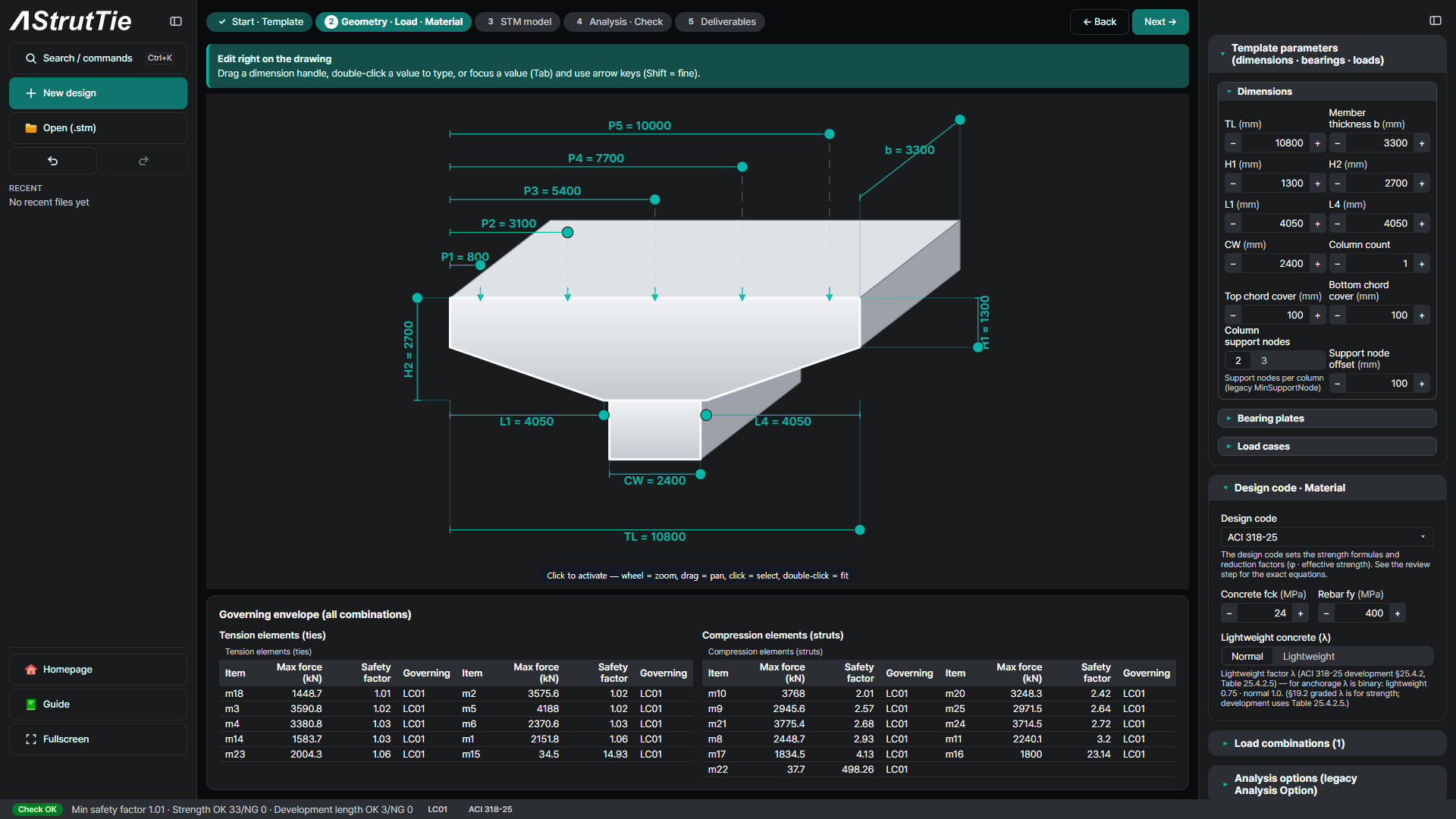
- Coping dimensions, bearing plates & service loads — entered in the template (see the drawing below)
The problem
A single-column pier coping carries the girder bearing reactions out to the column. Its overall geometry, bearings and loads define the design — typed straight onto the drawing.
Build the model — template → strut-and-tie
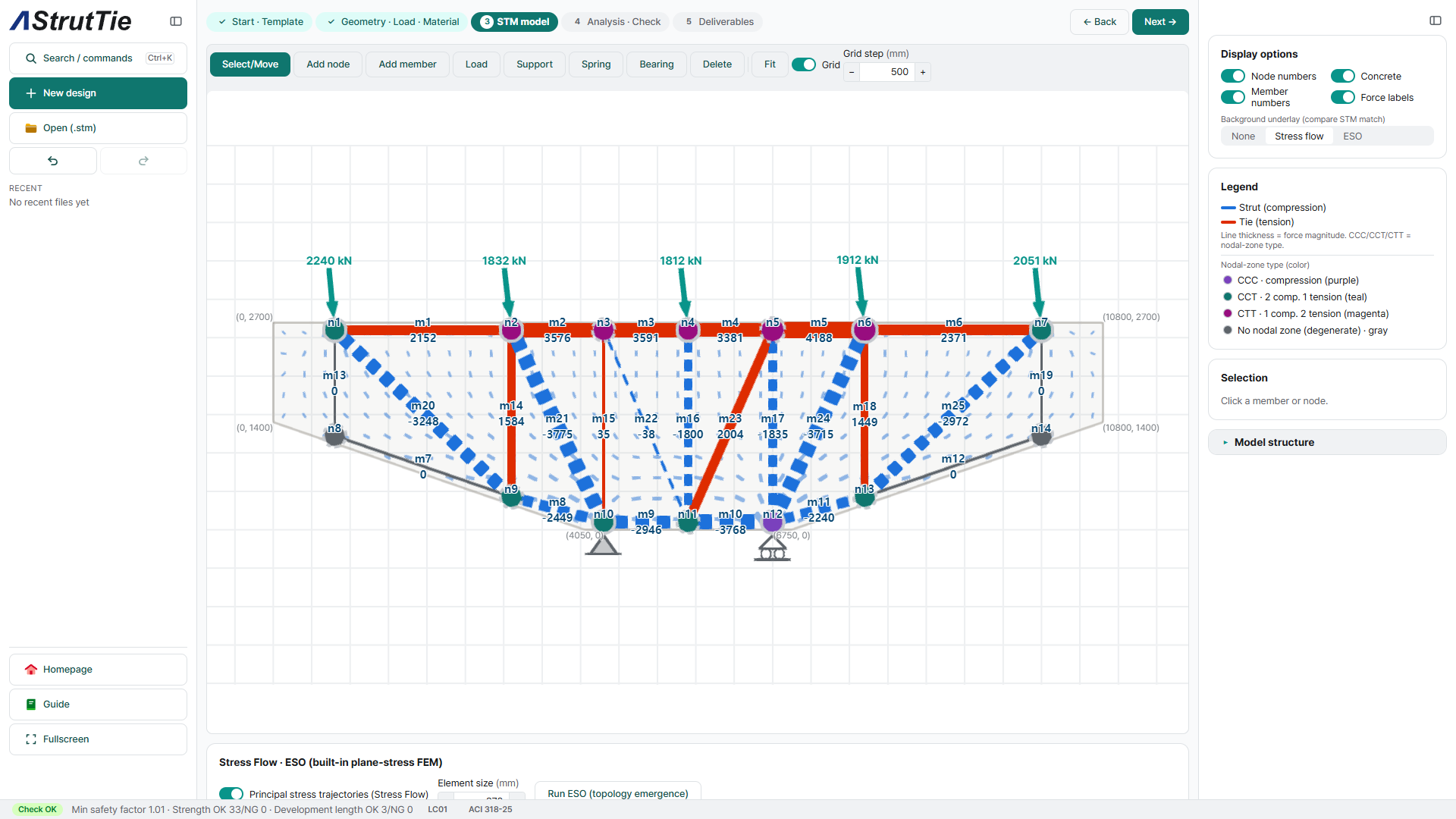
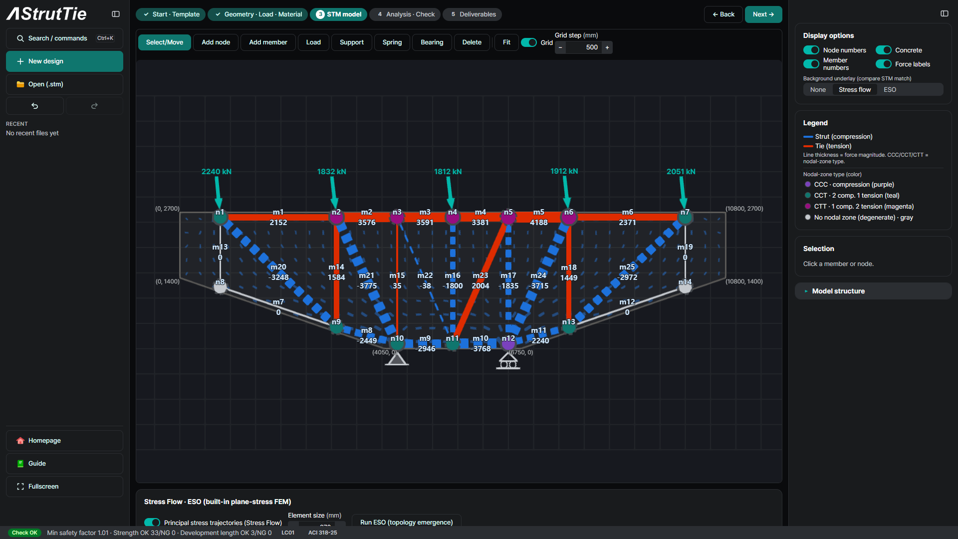
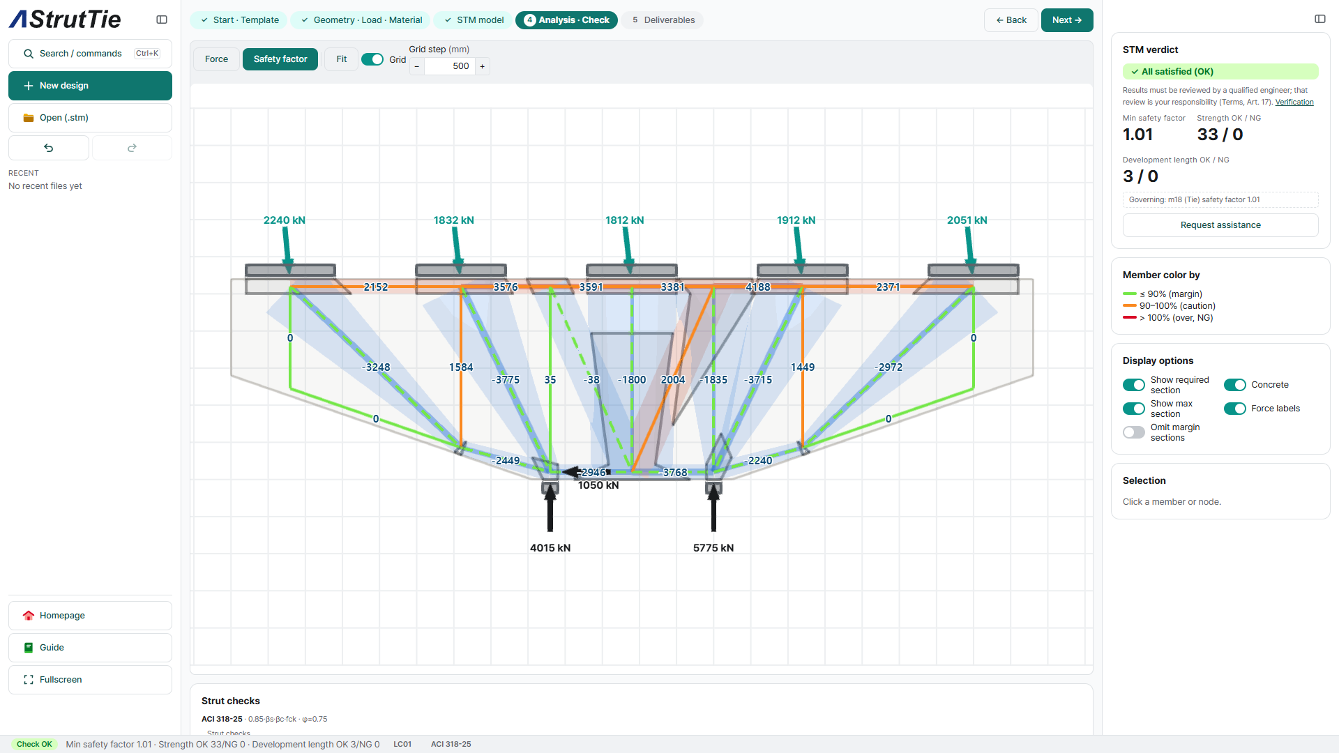
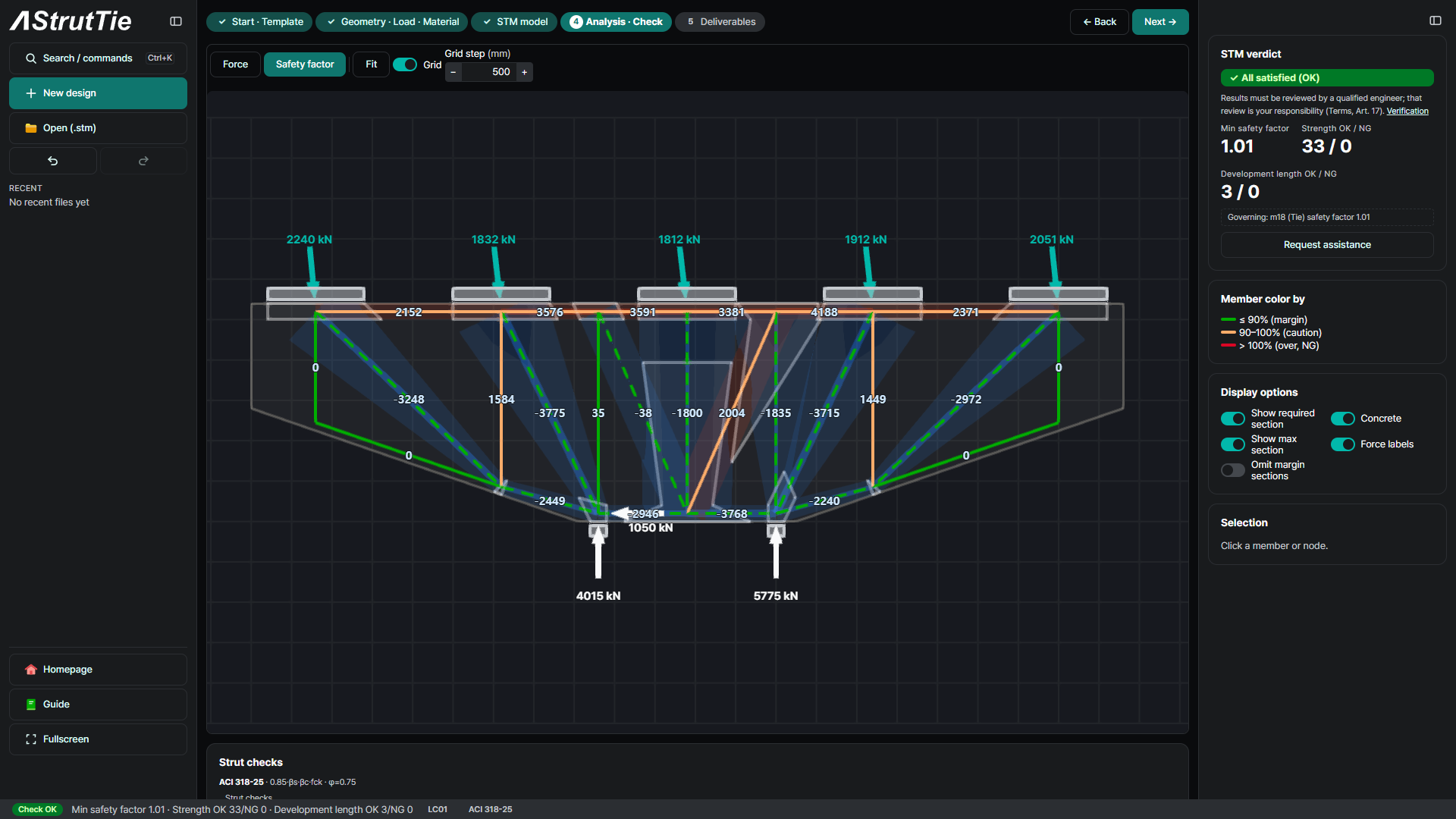
The pier-coping template builds a strut-and-tie model automatically: struts (compression, dashed), ties (tension, solid), and nodal zones typed CCC / CCT / CTT. It is then refined to follow the load path.
Analyze & check — every member, every combination
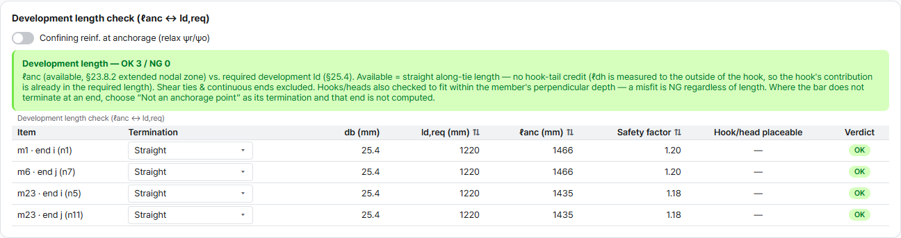
Analysis returns the member force Fu in every strut and tie, then checks all of them against the code. Here: 33 / 33 strength checks satisfied, minimum safety factor 1.01 (governing tie m18), and all 3 development length checks pass.
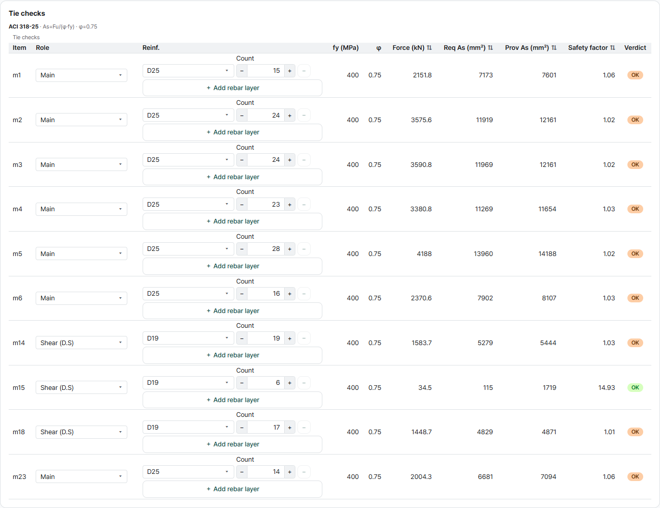
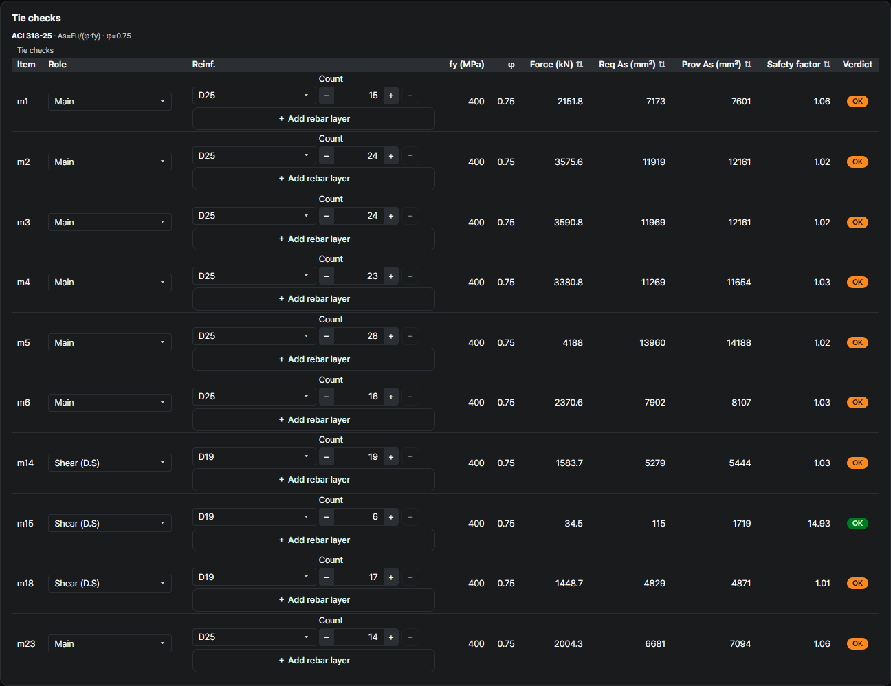
Tie check — required reinforcement
ACI 318-25Required steel As,req is compared with the provided bars (size × count). φ = 0.75, fy = 400 MPa.
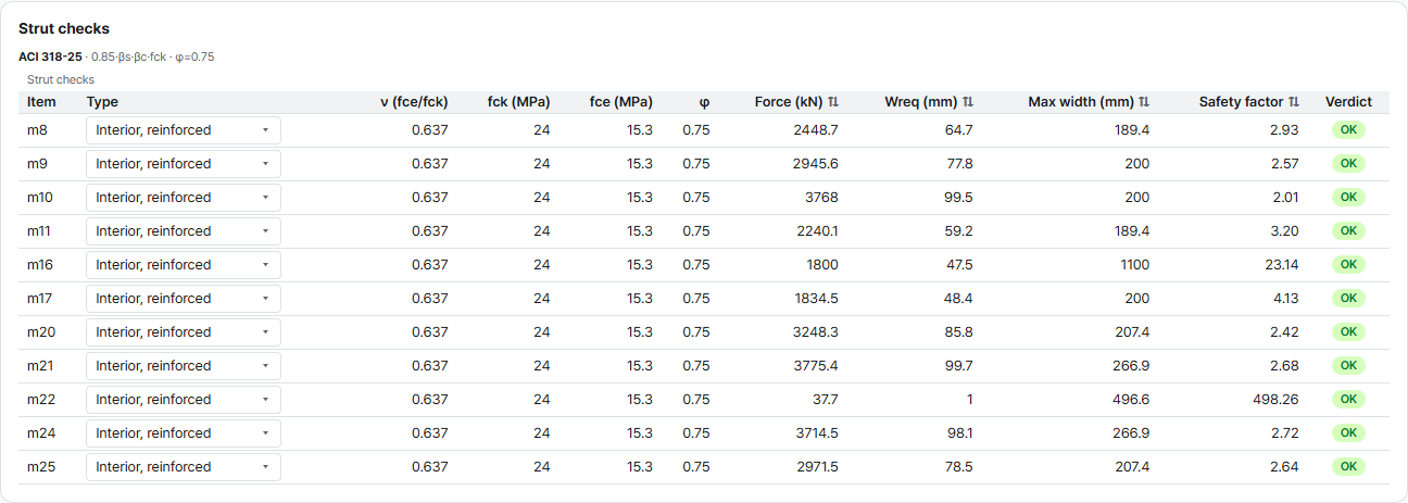
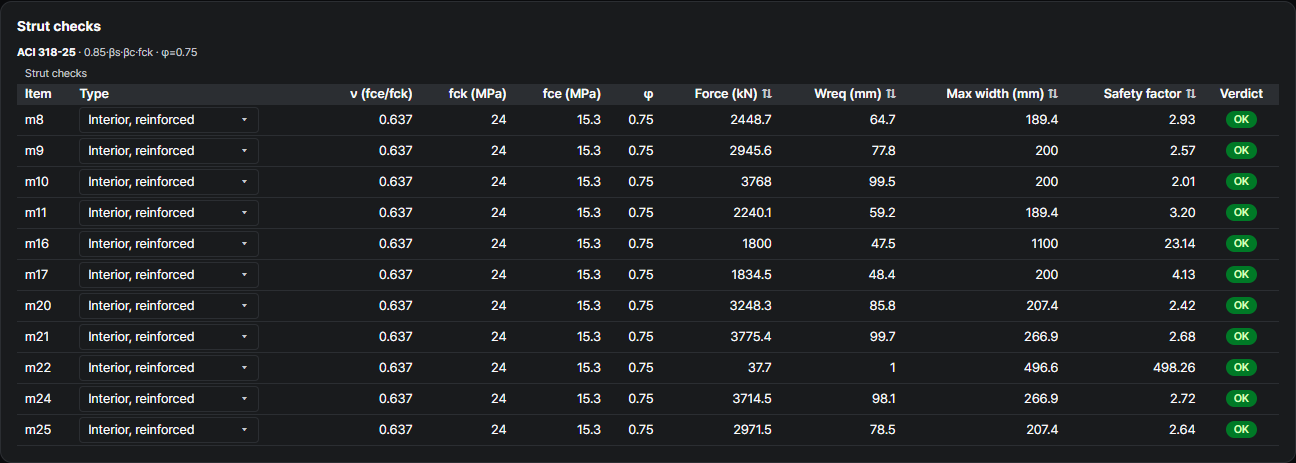
Strut check — effective strength & width
ACI 318-25Effective strength depends on strut type — Boundary (fce = 0.85 fck = 20.4 MPa) or Interior, reinforced (0.637 fck = 15.3 MPa). The required width must fit the available width.
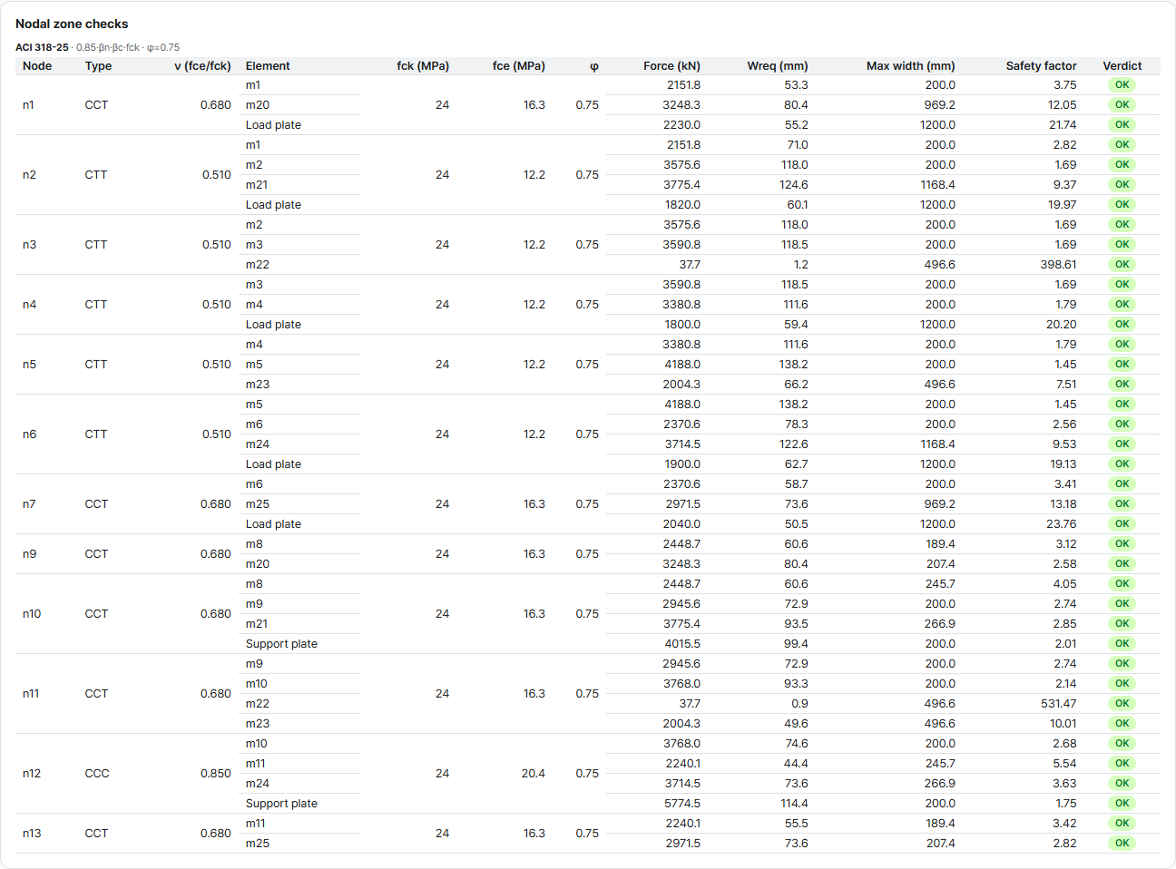
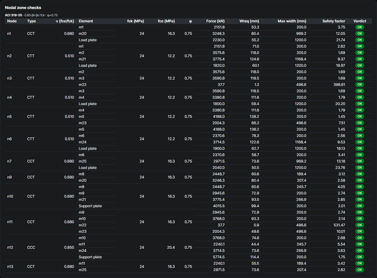
Nodal-zone check — by node type
ACI 318-25| Node | βn | fce (MPa) |
|---|---|---|
| CCC | 1.0 | 20.4 |
| CCT | 0.8 | 16.3 |
| CTT | 0.6 | 12.2 |
Development length check — anchorage at the node
ACI 318-25 §23.8.2 · §25.4The tie must be anchored at the node: the available anchorage ℓanc (§23.8.2, extended nodal zone) must reach the required development length ℓd (§25.4). Available = straight length along the tie — no hook-tail credit: ℓdh is measured to the outside of the hook, so the hook's contribution is already in the required length.
These are the same checks AStrutTie runs — and Technical Book Example 01 is one of the cases our verification gate holds the engine to, unsafe-side zero. How we verify →
Try it on your own numbers
Open AStrutTie in your browser, sign in with your email and start from the same template. The Free plan needs no installation and no card.