A worked example — a two-column pile cap on 21 piles
Two columns 6.4 m apart stand on one pile cap, 10.9 m long and 1.5 m deep, carried by 21 piles in three rows of seven. Between the columns the piles push the cap up and it bends the other way. This is Example 2.2 of the AStrutTie 2020 Technical Book, opened as a built-in example in the current AStrutTie and checked under ACI 318-25: every check value the book prints comes out the same, and where the template's truss put diagonals into tension they were turned round, as the book does.
Problem data and check values are from the AStrutTie 2020 Technical Book, Example 02-2.2 (two-column pile foundation, ACI 318-19). The example ships with the app; the model and every check below were run in the current AStrutTie under ACI 318-25.
Given
- f′c = 24 MPa · fy = 300 MPa · φ = 0.75
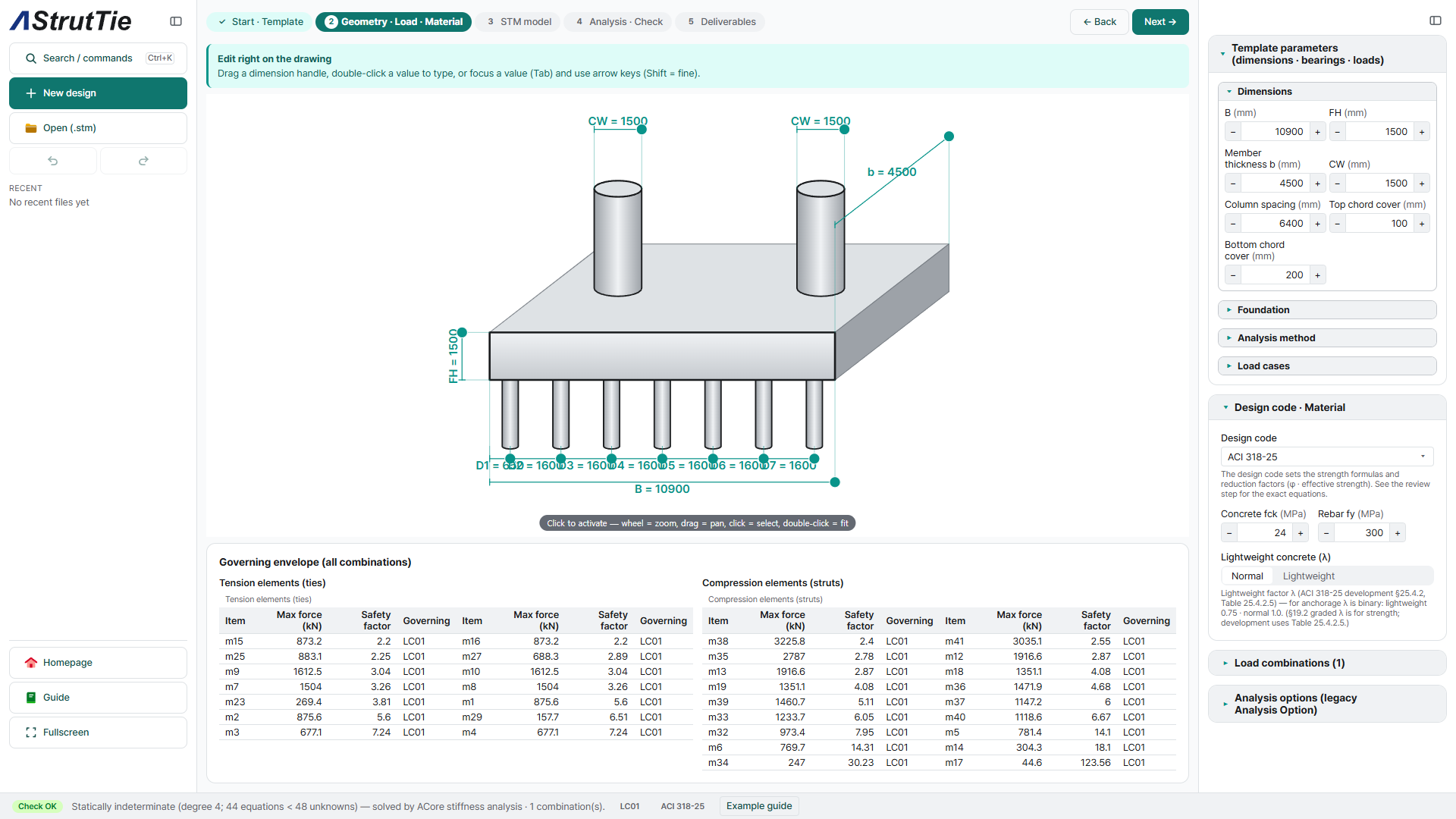
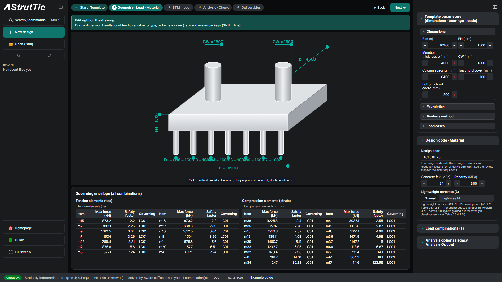
- Pile cap 10,900 × 4,500 mm, 1,500 mm deep · two columns 1,500 × 1,500 mm, 6,400 mm apart
- 21 piles of 508 mm diameter in three rows of seven, 650 mm from the ends and 1,600 mm apart
- Load case L1 (column 1): V = 5,700 kN · H = 900 kN · M = 5,300 kN·m · L2 (column 2): V = 5,300 kN · H = 1,000 kN · M = 5,200 kN·m · combination LC01 = L1 + L2
- Bars top 22-#7 · bottom 43-#8 · shear bars #6, 10 legs @ 400 mm vertical and 6 bars @ 400 mm horizontal
The problem
Two columns, two load cases: column 1 brings 5,700 kN with 900 kN and 5,300 kN·m, column 2 brings 5,300 kN with 1,000 kN and 5,200 kN·m, and the combination adds them. In the two-dimensional model the three piles of each row act together. The Technical Book example opens in AStrutTie with its dimensions, piles, loads, materials and bars already entered in the pile-footing template.
Build the model — the template's truss, four diagonals turned
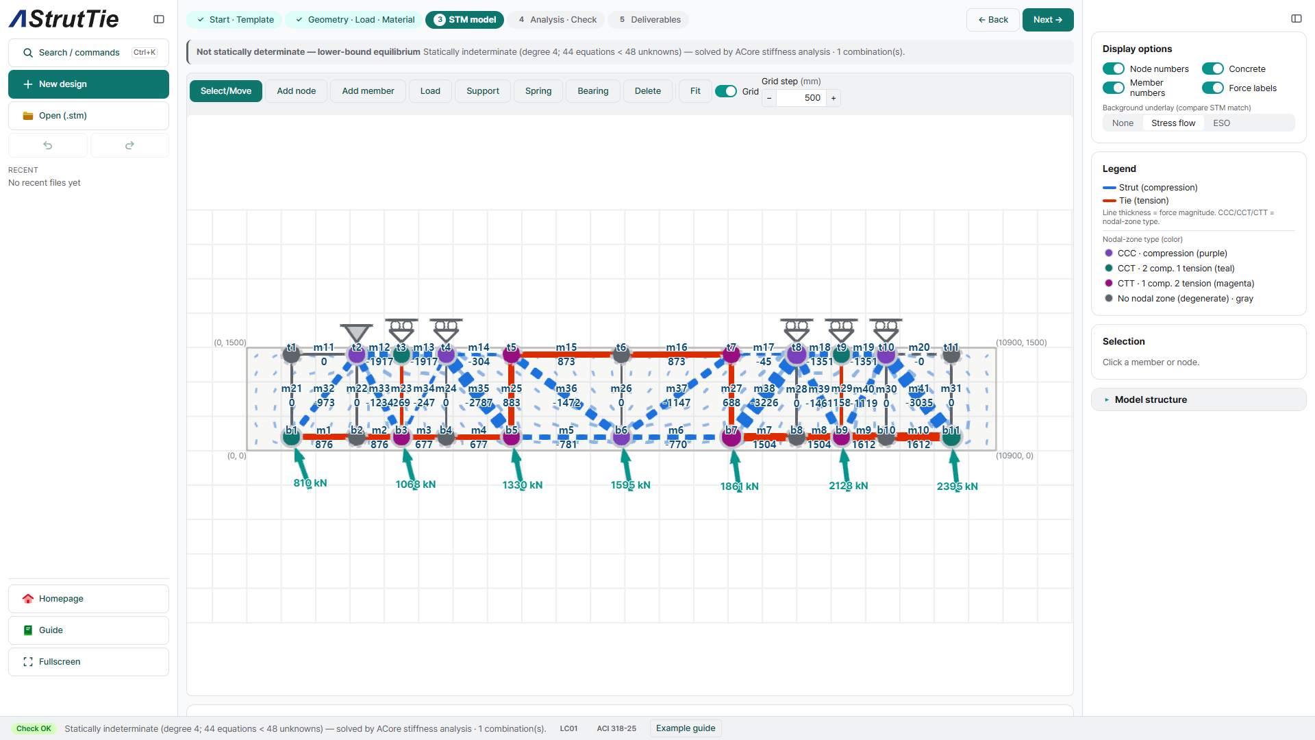
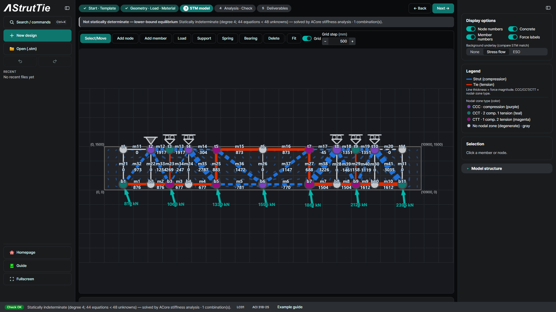
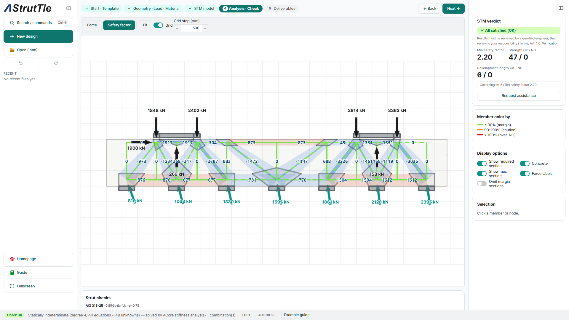
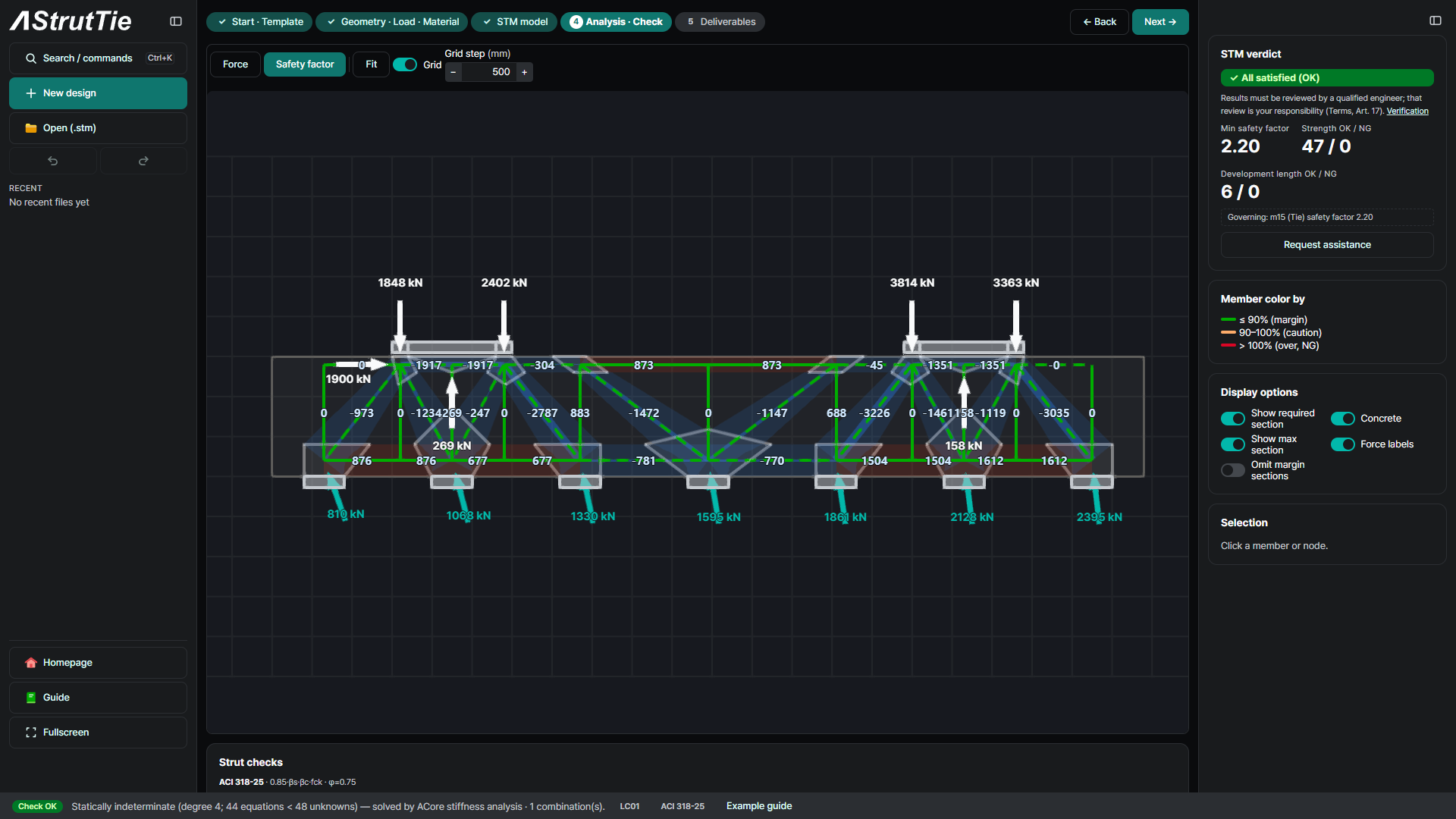
The template puts the top chord 100 mm below the top and the bottom chord 200 mm above the bottom, the book's setting, with three nodes under each column and a vertical at every node: 22 nodes and 41 members, the same counts as the book's final model. As in the book, the columns are the supports and the pile reactions come in as loads along the bottom chord, from 810 kN at one end to 2,395 kN at the other. Solved as built, three of the template's diagonals — m33, m39 and m40 — are in tension, and the book has no bars in that direction, so with no steel to carry the tension they fail. The book met the same thing: after its first optimized analysis one diagonal (E28) went into tension, and it changed that member's direction and re-ran a normal analysis. The three diagonals were turned the same way, to the other diagonal of their panels; on the re-run m34 went into tension and was turned too, and no diagonal is in tension after that. The built-in example opens with these four already turned. The truss is statically indeterminate to the fourth degree, so the app solves it by stiffness analysis. The largest bottom-chord tension is 1,612.5 kN, the book's E40 exactly; the largest compression is 3,225.8 kN in diagonal m38 against 3,671.8 kN in the book's top chord (−12.1%).
Analyze & check — every member, every node
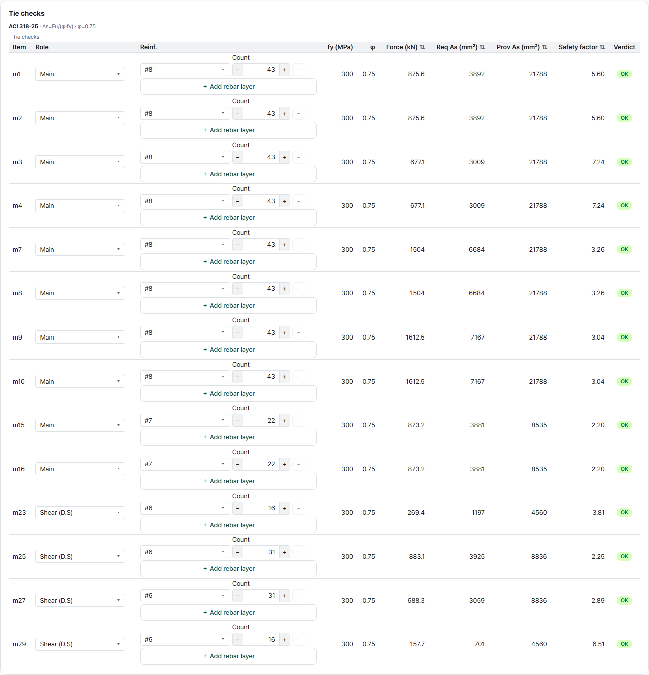
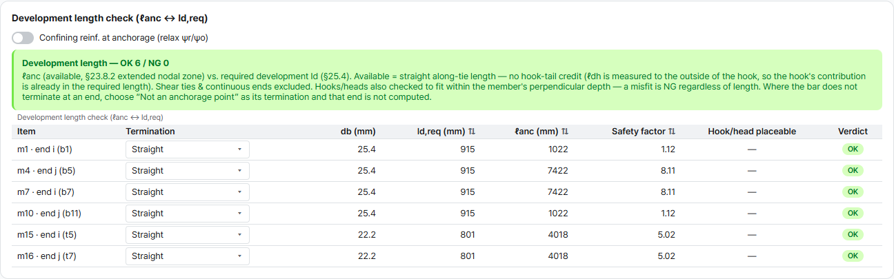
47 of 47 strength checks pass. The minimum safety factor is 2.20, on the top-chord ties m15 and m16 between the columns. Every tie end is anchored too: 6 of 6 development length checks pass.
Tie check — required reinforcement
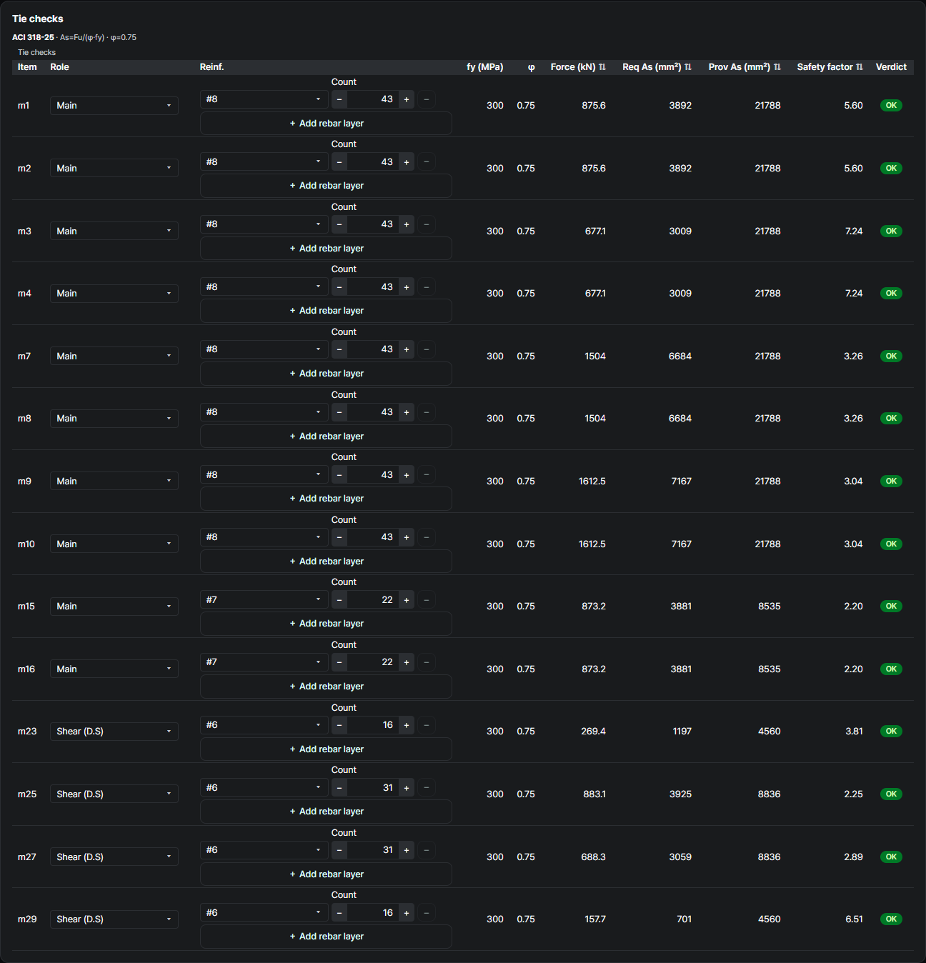
ACI 318-25Between the columns the top chord is in tension: m15 and m16 carry 873.2 kN and need 3,881 mm²; the 22-#7 top bars give 8,535 mm² (2.20). Under and beyond the columns the bottom chord takes the tension, up to 1,612.5 kN in m9 and m10, needing 7,167 mm² of the 21,788 mm² of 43-#8 (3.04) — the book's T40 at 1,612.49 kN needing 7,166.64 mm². The vertical ties are the shear reinforcement; the most loaded, m25 on the inner side of column 1, carries 883.1 kN against 31 legs of #6, 8,836 mm² (2.25).
Strut check — effective strength & width
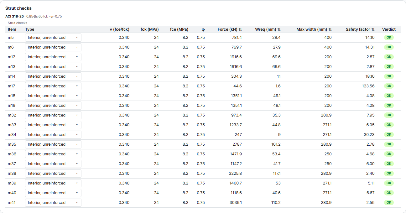
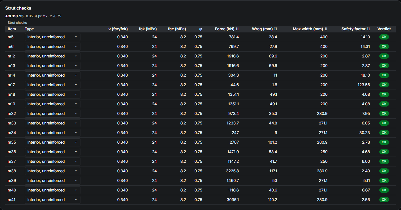
ACI 318-25 §23.4 · §23.5The shear bars, #6 at 400 mm both ways, give ρ ≈ 0.0016 vertically and 0.0009 horizontally, below the 0.0025 per direction that §23.5 asks for βs = 0.75. Every strut is therefore taken as βs = 0.40, as in the Technical Book (which used 1.00 for one strut, E28): fce = 8.16 MPa. The most loaded strut is the diagonal m38 down from column 2, 3,225.8 kN, needing 117 mm of the 281 mm available (2.40). Two diagonals carry the book's forces exactly: m32 at 973.4 kN (E12) and m41 at 3,035.1 kN (E30).
Nodal-zone check — by node type
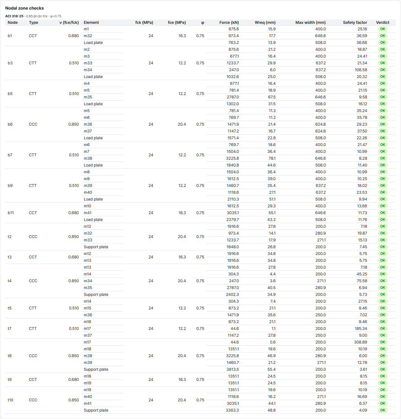
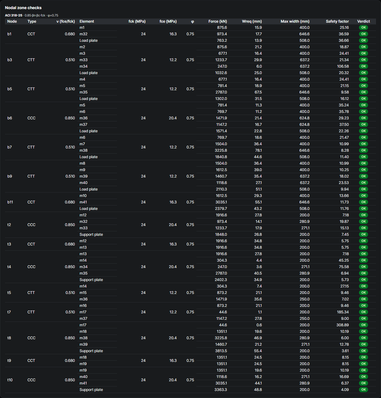
ACI 318-25The tightest node is t8, the inner support under column 2: its bearing face needs 55.4 of 200 mm (3.61). The book's check of node N3, face C-3 with 3,671.8 kN needing 53.3 mm, is reproduced exactly in the app's comparison.
| Node | βn | fce (MPa) |
|---|---|---|
| CCC | 1.0 | 20.4 |
| CCT | 0.8 | 16.3 |
| CTT | 0.6 | 12.2 |
Development length check — anchorage at the nodes
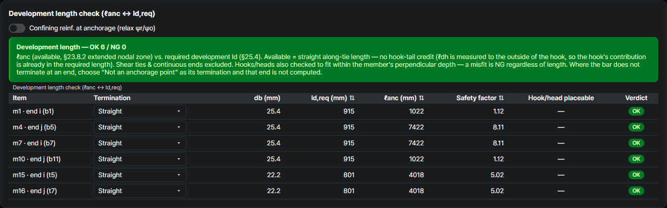
ACI 318-25 §23.8.2 · §25.4The bottom bars end over the first pile row, 650 mm from the ends of the cap. Straight, a #8 bar needs ℓd = 915 mm, and the extended nodal zone leaves 1,022 mm (1.12). The top-chord tie between the columns has 4,018 mm available against 801 mm (5.02). All six tie ends pass. The Technical Book's check tables for this example do not cover anchorage.
What changes from the Technical Book
ACI 318-19 → ACI 318-25Same cap, same loads, same bars. The strength equations and φ are the same in both editions, so every value the book's check tables print comes out the same. The model is the template's, with the book's own fix applied where diagonals went into tension. The struts keep the book's βs = 0.40 because the cap lacks §23.5 reinforcement, and the app checks the anchorage of every tie end; all pass here.
| Check | Technical Book (2020 · ACI 318-19) | This example — ACI 318-25 | Why |
|---|---|---|---|
| Values that must match (8) | T40 1,612.49 kN → 7,166.64 mm² · S3 3,671.8 kN → 133.3 mm · N3 C-3 3,671.8 kN → 53.3 mm … | 8 of 8 the same | Same strength equations and φ |
| Model | Final model after optimized analysis — 22 nodes · 41 elements | Template model — 22 nodes · 41 members · indeterminate (4) | Same counts, different layout |
| Diagonal in tension | E28 (+45.6 kN) after the first optimized analysis — turned and re-run | m33 · m34 · m39 · m40 — turned the same way | The book's own procedure |
| Largest bottom-chord tension | E40 1,612.5 kN | m9 · m10 1,612.5 kN | Same |
| Largest compression | E3 3,671.8 kN (top chord) | m38 3,225.8 kN (diagonal, −12.1%) | Different layout |
| Bars, top 22-#7 · bottom 43-#8 | 8,534.90 · 21,788.53 mm² | 8,535 · 21,788 mm² · 2.20 · 3.04 | Same bars |
| Shear reinforcement | 10-#6 · weff 950.0 mm · φFn 1,523.1 kN ≥ 1,299.05 kN | m25 883.1 kN · 8,836 mm² (2.25) | Vertical ties at the template's positions |
| βs of the struts | 0.40 (E28: 1.00) | 0.40 | #6 @ 400 mm gives ρ ≈ 0.0016 / 0.0009 < 0.0025 (§23.5) |
| Anchorage | Not in the check tables | 6 of 6 tie ends pass (bottom 1,022 ≥ 915 mm) | The app checks every tie end |
These are the checks AStrutTie runs on every model — here on an example from the AStrutTie 2020 Technical Book, opened in the current app, with every check value the book prints reproduced and every difference traced to the model or a reinforcement detail. How we verify →
Try it on your own numbers
Open AStrutTie in your browser, sign in with your email and start from the same template. The Free plan needs no installation and no card.